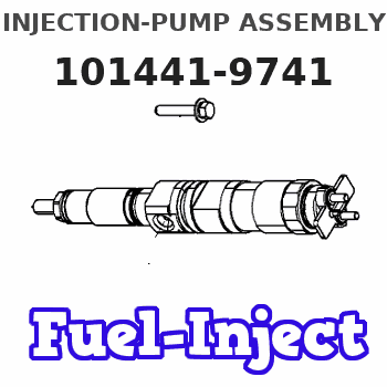
Information injection-pump assembly
ZEXEL
101441-9741
1014419741
NISSAN-DIESEL
1679090308
1679090308
Rating:
Cross reference number
ZEXEL
101441-9741
1014419741
NISSAN-DIESEL
1679090308
1679090308
Zexel num
Bosch num
Firm num
Name
101441-9741
1679090308 NISSAN-DIESEL
INJECTION-PUMP ASSEMBLY
SD25 * K
SD25 * K
Calibration Data:
Adjustment conditions
Test oil
1404 Test oil ISO4113 or {SAEJ967d}
1404 Test oil ISO4113 or {SAEJ967d}
Test oil temperature
degC
40
40
45
Nozzle and nozzle holder
105780-8140
Bosch type code
EF8511/9A
Nozzle
105780-0000
Bosch type code
DN12SD12T
Nozzle holder
105780-2080
Bosch type code
EF8511/9
Opening pressure
MPa
17.2
Opening pressure
kgf/cm2
175
Injection pipe
Outer diameter - inner diameter - length (mm) mm 6-2-600
Outer diameter - inner diameter - length (mm) mm 6-2-600
Tester oil delivery pressure
kPa
157
157
157
Tester oil delivery pressure
kgf/cm2
1.6
1.6
1.6
Direction of rotation (viewed from drive side)
Right R
Right R
Injection timing adjustment
Direction of rotation (viewed from drive side)
Right R
Right R
Injection order
1-3-4-2
Pre-stroke
mm
2.3
2.25
2.35
Beginning of injection position
Drive side NO.1
Drive side NO.1
Difference between angles 1
Cal 1-3 deg. 90 89.5 90.5
Cal 1-3 deg. 90 89.5 90.5
Difference between angles 2
Cal 1-4 deg. 180 179.5 180.5
Cal 1-4 deg. 180 179.5 180.5
Difference between angles 3
Cyl.1-2 deg. 270 269.5 270.5
Cyl.1-2 deg. 270 269.5 270.5
Injection quantity adjustment
Adjusting point
A
Rack position
10.8
Pump speed
r/min
900
900
900
Average injection quantity
mm3/st.
39.9
38.9
40.9
Max. variation between cylinders
%
0
-2.5
2.5
Basic
*
Fixing the lever
*
Injection quantity adjustment_02
Adjusting point
B
Rack position
10.1
Pump speed
r/min
1200
1200
1200
Average injection quantity
mm3/st.
37
34
40
Max. variation between cylinders
%
0
-4
4
Fixing the lever
*
Injection quantity adjustment_03
Adjusting point
C
Rack position
6.8+-0.5
Pump speed
r/min
300
300
300
Average injection quantity
mm3/st.
8.2
7.1
9.3
Max. variation between cylinders
%
0
-15
15
Fixing the rack
*
Timer adjustment
Pump speed
r/min
500
Advance angle
deg.
0.5
Timer adjustment_02
Pump speed
r/min
900
Advance angle
deg.
1.8
1.3
2.3
Timer adjustment_03
Pump speed
r/min
1300
Advance angle
deg.
4
3.5
4.5
Timer adjustment_04
Pump speed
r/min
-
Advance angle
deg.
5
5
5
Remarks
Measure the actual speed, stop
Measure the actual speed, stop
Test data Ex:
Governor adjustment
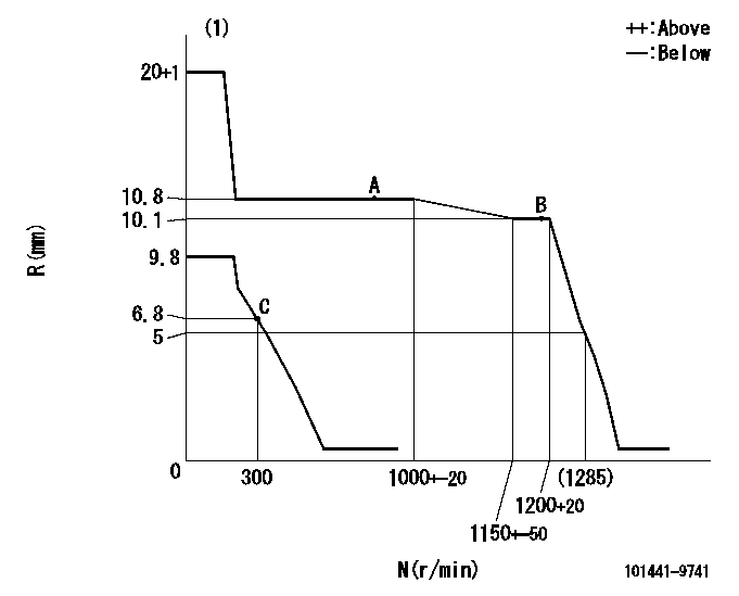
N:Pump speed
R:Rack position (mm)
(1)Notch fixed: K
----------
K=20
----------
----------
K=20
----------
Speed control lever angle
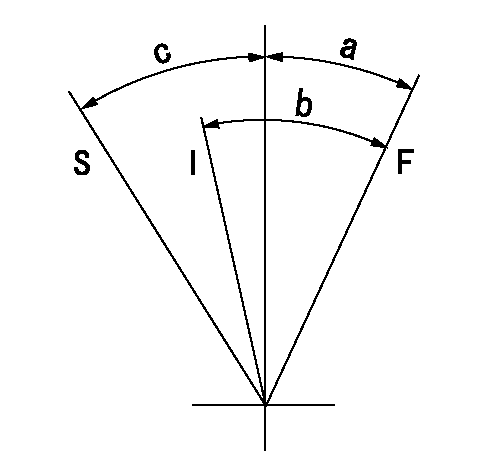
F:Full speed
I:Idle
S:Stop
----------
----------
a=(15deg)+-5deg b=(32deg)+-5deg c=32deg+-3deg
----------
----------
a=(15deg)+-5deg b=(32deg)+-5deg c=32deg+-3deg
Stop lever angle

N:Pump normal
S:Stop the pump.
(1)Normal
----------
----------
a=19deg+-5deg b=53deg+-5deg
----------
----------
a=19deg+-5deg b=53deg+-5deg
Timing setting

(1)Pump vertical direction
(2)Position of gear mark 'Y' at No 1 cylinder's beginning of injection
(3)B.T.D.C.: aa
(4)-
----------
aa=20deg
----------
a=(130deg)
----------
aa=20deg
----------
a=(130deg)
Information:
The results of the preceding procedure are in the following list:
The output corresponds to the desired pressure range. Stop.
The output does not correspond to the desired pressure range. Proceed to 3.
Calibrate the transducer. This assumes that the transducer is mounted on the engine.
Turn the isolation valve on the transducer mounting. This isolates the transducer from the engine. An arrow on the valve indicates the direction of flow. See illustration 2.
Apply a pressure that is equal to 4 mA to the transducer. See table 1. See the pressure port connection in illustration 2.
Monitor the ammeter. Adjust the zero dial until the ammeter reads 4mA. See the location of the zero dial that is in illustration 1.
Apply the pressure that is equal to 20mA to the transducer. See table 1. See the pressure port connection in illustration 2.Note: The full range of pressure may not be available. Use partial pressure. Use the highest possible pressure. This will yield the best accuracy. See table 1.
Monitor the ammeter. Adjust the zero dial until the ammeter reads 20mA. See the location of the zero dial that is in illustration 1.
Apply the pressure that is equal to 4mA to the transducer. Verify that the ammeter displays 4mA.The results of the preceding procedure are in the following list:
The output corresponds to the desired pressure range. The transducer is calibrated. Stop.
The output does not correspond to the desired pressure range. Proceed to 4.
Reapply the pressure.
Apply the pressure that is equal to 4mA to the transducer. See table 1. See the pressure port connection in illustration 2.
Monitor the ammeter. Adjust the zero dial until the ammeter reads 4mA. See the location of the zero dial that is in illustration 1.
Apply the pressure that is equal to 20mA to the transducer. See table 1. See the pressure port connection in illustration 2.Note: The full range of pressure may not be available. Use partial pressure. Use the highest possible pressure. This will yield the best accuracy. See table 1.
Monitor the ammeter. Adjust the zero dial until the ammeter reads 20mA. See the location of the zero dial that is in illustration 1.
Apply the pressure that is equal to 4mA to the transducer. Verify that the ammeter displays 4mA.The results of the preceding procedure are in the following list:Note: Repeat the procedure several times in order to properly calibrate the transducer. Continue until the 4mA signal is correct and the 20mA signal is correct.
The output corresponds to the desired pressure range. The transducer is calibrated. Stop.
The output does not correspond to the desired pressure range. Replace the transducer. Verify that the repair resolves the problem. Stop.
Have questions with 101441-9741?
Group cross 101441-9741 ZEXEL
Nissan-Diesel
Nissan-Diesel
Nissan-Diesel
Daewoo
Nissan-Diesel
101441-9741
1679090308
INJECTION-PUMP ASSEMBLY
SD25
SD25