Information injection-pump assembly
ZEXEL
101441-9600
1014419600
NISSAN-DIESEL
1670090071
1670090071

Rating:
Cross reference number
ZEXEL
101441-9600
1014419600
NISSAN-DIESEL
1670090071
1670090071
Zexel num
Bosch num
Firm num
Name
Calibration Data:
Adjustment conditions
Test oil
1404 Test oil ISO4113 or {SAEJ967d}
1404 Test oil ISO4113 or {SAEJ967d}
Test oil temperature
degC
40
40
45
Nozzle and nozzle holder
105780-8140
Bosch type code
EF8511/9A
Nozzle
105780-0000
Bosch type code
DN12SD12T
Nozzle holder
105780-2080
Bosch type code
EF8511/9
Opening pressure
MPa
17.2
Opening pressure
kgf/cm2
175
Injection pipe
Outer diameter - inner diameter - length (mm) mm 6-2-600
Outer diameter - inner diameter - length (mm) mm 6-2-600
Tester oil delivery pressure
kPa
157
157
157
Tester oil delivery pressure
kgf/cm2
1.6
1.6
1.6
Direction of rotation (viewed from drive side)
Right R
Right R
Injection timing adjustment
Direction of rotation (viewed from drive side)
Right R
Right R
Injection order
1-3-4-2
Pre-stroke
mm
2.3
2.25
2.35
Beginning of injection position
Drive side NO.1
Drive side NO.1
Difference between angles 1
Cal 1-3 deg. 90 89.5 90.5
Cal 1-3 deg. 90 89.5 90.5
Difference between angles 2
Cal 1-4 deg. 180 179.5 180.5
Cal 1-4 deg. 180 179.5 180.5
Difference between angles 3
Cyl.1-2 deg. 270 269.5 270.5
Cyl.1-2 deg. 270 269.5 270.5
Injection quantity adjustment
Adjusting point
-
Rack position
12.5
Pump speed
r/min
1400
1400
1400
Average injection quantity
mm3/st.
41.4
40.4
42.4
Max. variation between cylinders
%
0
-2.5
2.5
Basic
*
Fixing the rack
*
Injection quantity adjustment_02
Adjusting point
-
Rack position
9+-0.5
Pump speed
r/min
600
600
600
Average injection quantity
mm3/st.
10
8.9
11.1
Max. variation between cylinders
%
0
-15
15
Fixing the rack
*
Timer adjustment
Pump speed
r/min
550--
Advance angle
deg.
0
0
0
Remarks
Start
Start
Timer adjustment_02
Pump speed
r/min
500
Advance angle
deg.
0.5
Timer adjustment_03
Pump speed
r/min
1500
Advance angle
deg.
3
2.5
3.5
Remarks
Finish
Finish
Test data Ex:
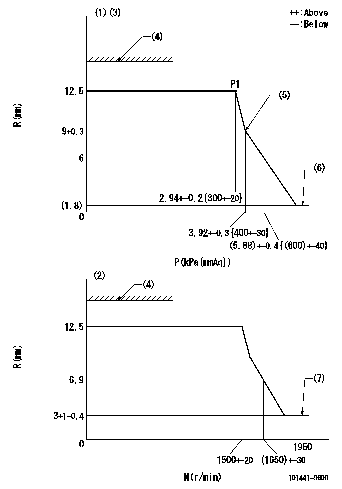
Governor adjustment

N:Pump speed
R:Rack position (mm)
P:Negative pressure
(1)Pneumatic governor
(2)Mechanical governor
(3)Acting negative pressure: P1
(4)RACK LIMIT: RAL
(5)Beginning of idle sub spring operation: L1
(6)With stopper disk.
(7)Injection quantity Q = Q1 or less
----------
RAL=16.7-0.3mm L1=9+0.3mm Q1=3mm3/st
----------
----------
RAL=16.7-0.3mm L1=9+0.3mm Q1=3mm3/st
----------
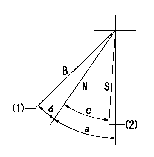
Speed control lever angle

B:When boosted
N:Normal
S:Stop
(1)Rack position = aa
(2)Rack position bb
----------
aa=(17)mm bb=(1.8)mm
----------
a=29.5deg+-5deg b=9deg+-5deg c=21.5deg+-3deg
----------
aa=(17)mm bb=(1.8)mm
----------
a=29.5deg+-5deg b=9deg+-5deg c=21.5deg+-3deg
Timing setting

(1)Pump vertical direction
(2)Position of gear mark 'Y' at No 1 cylinder's beginning of injection
(3)B.T.D.C.: aa
(4)-
----------
aa=18deg
----------
a=(100deg)
----------
aa=18deg
----------
a=(100deg)
Information:
Replacing a Power Supply
Disconnect the power supply.
To avoid damage to electronic components, do not remove the processor from the SLC 5/04 Chassis until all power is removed from the power supply.Do not expose memory modules to surfaces or areas that may typically hold an electrostatic charge.
Remove the two retaining screws that secure the power supply to the chassis.
Remove the power supply from the chassis.
To avoid potential damage to the processor, handle all modules by the ends of the carrier or edges of the plastic housing. Skin oil or dirt can corrode metallic surfaces, inhibiting electrical contact.
Align the new power supply and the guides in the chassis.
Gently slide the power supply in the chassis. Secure the top retainer clips and secure the bottom retainer clips.
Install the two retaining screws that secure the power supply to the chassis.
Install a wire tie in order to secure your wiring.
Cover any unused slots. This protects the chassis.
Illustration 1 g00563308
Verify that the new power supply corrects the problem.