Information injection-pump assembly
BOSCH
9 400 610 077
9400610077
ZEXEL
101441-9490
1014419490
NISSAN-DIESEL
1670025G01
1670025g01

Rating:
Service parts 101441-9490 INJECTION-PUMP ASSEMBLY:
1.
_

6.
COUPLING PLATE
7.
COUPLING PLATE
8.
_
9.
_
11.
Nozzle and Holder
16600-36W00
12.
Open Pre:MPa(Kqf/cm2)
9.8{100}

15.
NOZZLE SET
Include in #1:
101441-9490
as INJECTION-PUMP ASSEMBLY
Include in #2:
105866-5160
as _
Cross reference number
BOSCH
9 400 610 077
9400610077
ZEXEL
101441-9490
1014419490
NISSAN-DIESEL
1670025G01
1670025g01
Zexel num
Bosch num
Firm num
Name
101441-9490
9 400 610 077
1670025G01 NISSAN-DIESEL
INJECTION-PUMP ASSEMBLY
SD23 * K
SD23 * K
Calibration Data:
Adjustment conditions
Test oil
1404 Test oil ISO4113 or {SAEJ967d}
1404 Test oil ISO4113 or {SAEJ967d}
Test oil temperature
degC
40
40
45
Nozzle and nozzle holder
105780-8140
Bosch type code
EF8511/9A
Nozzle
105780-0000
Bosch type code
DN12SD12T
Nozzle holder
105780-2080
Bosch type code
EF8511/9
Opening pressure
MPa
17.2
Opening pressure
kgf/cm2
175
Injection pipe
Outer diameter - inner diameter - length (mm) mm 6-2-600
Outer diameter - inner diameter - length (mm) mm 6-2-600
Tester oil delivery pressure
kPa
157
157
157
Tester oil delivery pressure
kgf/cm2
1.6
1.6
1.6
Direction of rotation (viewed from drive side)
Right R
Right R
Injection timing adjustment
Direction of rotation (viewed from drive side)
Right R
Right R
Injection order
1-3-4-2
Pre-stroke
mm
2.15
2.1
2.2
Beginning of injection position
Drive side NO.1
Drive side NO.1
Difference between angles 1
Cal 1-3 deg. 90 89.5 90.5
Cal 1-3 deg. 90 89.5 90.5
Difference between angles 2
Cal 1-4 deg. 180 179.5 180.5
Cal 1-4 deg. 180 179.5 180.5
Difference between angles 3
Cyl.1-2 deg. 270 269.5 270.5
Cyl.1-2 deg. 270 269.5 270.5
Injection quantity adjustment
Adjusting point
-
Rack position
12
Pump speed
r/min
1000
1000
1000
Average injection quantity
mm3/st.
38.8
37.8
39.8
Max. variation between cylinders
%
0
-2.5
2.5
Basic
*
Fixing the rack
*
Injection quantity adjustment_02
Adjusting point
-
Rack position
8.2+-0.5
Pump speed
r/min
300
300
300
Average injection quantity
mm3/st.
8
6.9
9.1
Max. variation between cylinders
%
0
-15
15
Fixing the rack
*
Timer adjustment
Pump speed
r/min
550--
Advance angle
deg.
0
0
0
Remarks
Start
Start
Timer adjustment_02
Pump speed
r/min
500
Advance angle
deg.
0.5
Timer adjustment_03
Pump speed
r/min
1200
Advance angle
deg.
2
1.5
2.5
Timer adjustment_04
Pump speed
r/min
2150
Advance angle
deg.
7
6.5
7.5
Remarks
Finish
Finish
Test data Ex:
Governor adjustment
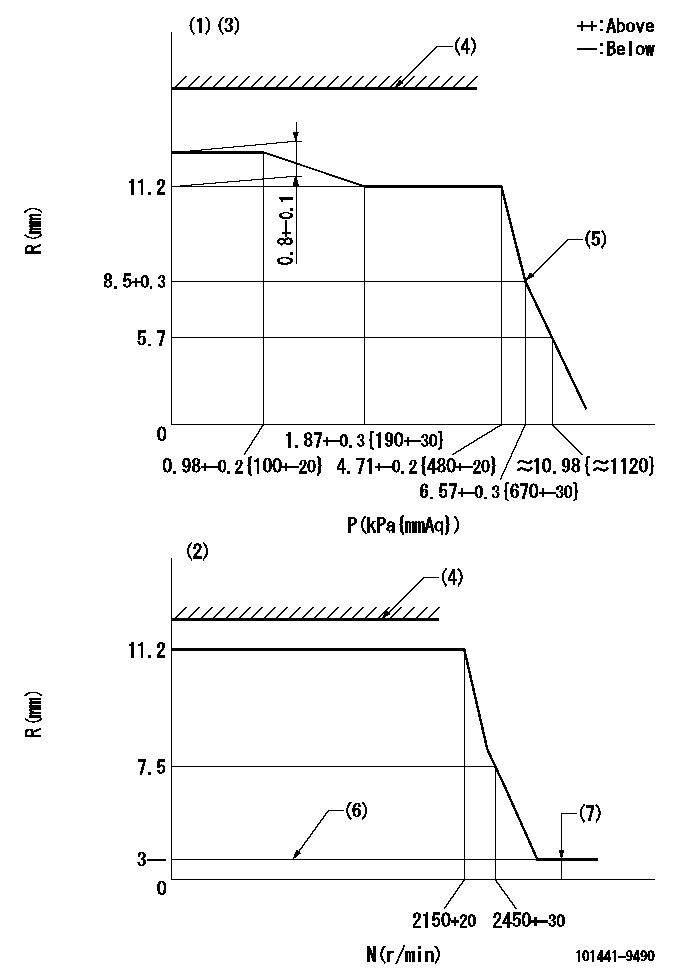
N:Pump speed
R:Rack position (mm)
P:Negative pressure
(1)Pneumatic governor
(2)Mechanical governor
(3)Acting negative pressure: P1
(4)RACK LIMIT: RAL
(5)Beginning of idle sub spring operation: L1
(6)Without stopper disk
(7)Injection quantity Q = Q1 or less (at N = N1)
----------
P1=2.94+-0.2kPa(300+-20mmAq) RAL=14.7-0.3mm L1=8.5+0.3mm Q1=3mm3/st N1=(2600)r/min
----------
----------
P1=2.94+-0.2kPa(300+-20mmAq) RAL=14.7-0.3mm L1=8.5+0.3mm Q1=3mm3/st N1=(2600)r/min
----------
Speed control lever angle
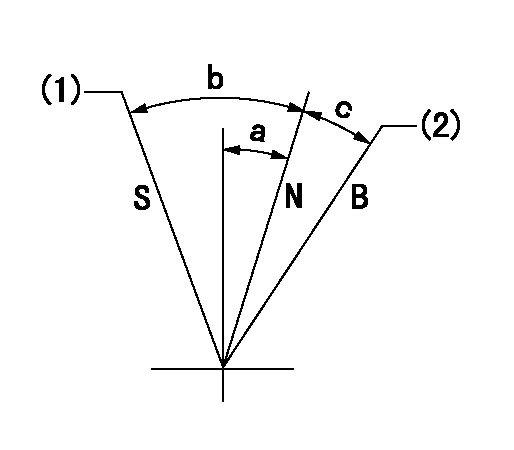
B:When boosted
N:Normal
S:Stop
(1)Rack position = aa
(2)Rack position corresponding to cc
----------
aa=0mm bb=15mm
----------
a=0deg+-5deg b=23deg+-3deg c=6deg+-5deg
----------
aa=0mm bb=15mm
----------
a=0deg+-5deg b=23deg+-3deg c=6deg+-5deg
0000001501 ACS
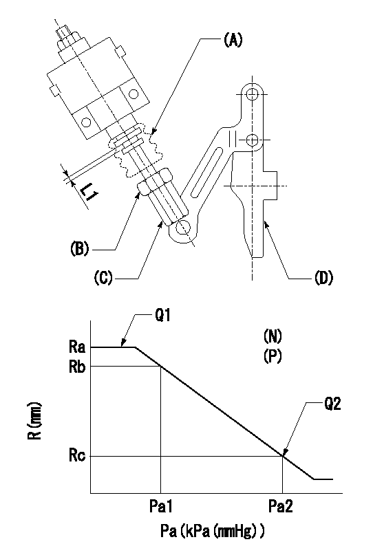
(N): Speed of the pump
(P): governor's negative pressure
(Pa): aneroid compensator's negative pressure
(A) rubber boot
(B) Nut
(c) Nut
(D) Lever
1. Aneroid compensator installation
(1)Turn nut (C) to adjust gap to L1. (Remove rubber boot at adjustment.)
(2)Lock using nut (B).
(3)After installation, the lever D must move smoothly when the lever D is moved to the excess fuel side, and R = R1 or more.
----------
L1=0.1~0.5mm R1=16mm
----------
N=1000r/min P=0.5kPa(50mmAq) Ra=12mm Rb=- Rc=(11.6)mm Pa1=8-5.3kPa(60-40mmHg) Pa2=16.7kPa(125mmHg) Q1=- Q2=35.9+-1cm3/1000st
----------
L1=0.1~0.5mm R1=16mm
----------
N=1000r/min P=0.5kPa(50mmAq) Ra=12mm Rb=- Rc=(11.6)mm Pa1=8-5.3kPa(60-40mmHg) Pa2=16.7kPa(125mmHg) Q1=- Q2=35.9+-1cm3/1000st
Timing setting

(1)Pump vertical direction
(2)Position of gear mark 'Y' at No 1 cylinder's beginning of injection
(3)B.T.D.C.: aa
(4)-
----------
aa=18deg
----------
a=(140deg)
----------
aa=18deg
----------
a=(140deg)
Information:
Problem 4
The starting motor remains engaged or the starting motor continues to run after the engine is running.
Check the components of the starting circuit.
Measure the voltages at terminal (TS-26) of the junction box while the engine is running.Result
The voltage at the terminal is zero volts.The problem is in the starting motor (SM), the pinion solenoid (PS), or the magnetic switch (MS). Repair the faulty component. STOP.
The voltage at the terminal is between 15 volts and 32 volts.The START terminals of the start/stop switch are normally closed. This is normal for an automatic start system. In a manual start system, the switches should be normally open. The switch is on terminals (SSS-1) and (SSS-2) for a normal start/stop switch. Repair the faulty switch. STOP.Problem 5
The engine shutdown occurs after the engine runs for more than 3 minutes.
Check the protection switches.
Remove the jumper that is between terminals (TS-9) and (TS-10) of the junction box.
If the engine is equipped with a low oil pressure indicator, disconnect the diode that is between terminals (TS-8) and (TS-10). The cathode lead of the diode should be connected to terminal (TS-10).
If the engine is equipped with a low oil pressure indicator, ensure that a jumper is not installed between terminals (TS-8) and (TS-9).
Start the engine.
Reconnect the jumper that is between terminals (TS-9) and (TS-10) of the junction box after the test is completed.Result
The engine starts and the engine runs.The problem is in the oil pressure switch or the water temperature contactor switch. Go to Step 5 of "Problem 1".
The engine starts but engine shutdown occurs immediately.Go to Step 1 of "Problem 3".
The engine starts and the engine runs but engine shutdown occurs after the engine runs for more than 3 minutes.Go to Step 2.
The engine cranks but the engine does not start.Go to Step 1 of "Problem 1".
Check the start/stop switch and slave relay (SR1).
Disconnect the wire in the junction box that connects terminal (SR1-85) of the slave relay (SR1) to terminal (TD-7) of the time delay relay (TD).
Crank the engine. Activate the emergency stop switch, if necessary.Result
The engine starts and the engine runs.The start/stop switch has a short circuit or a wiring problem is causing a voltage at terminal (TD-7). Reconnect the wire to the terminal. STOP.
Engine shutdown still occurs after several minutes.The contacts of (SR1) periodically close. The problem may also be with the governor or the fuel supply to the engine. Refer to the Engine Service Manual. If a 2301A Electric Governor is used, the SR1 contacts may be opening. Refer to 2301A Electric Governor Service Manual, SENR3585. Test SR1. Refer to Testing and Adjusting, "Slave Relay Test".Problem 6
Engine shutdown does not occur when a fault is detected.
Check the protection switches and the crank terminate switch of the electronic speed switch.
Reset circuit breaker (CB7).
Start the engine and run the engine at low idle.
Contact with electrical components can cause injury or death.Remove all jewelry and avoid contact with electrical components. Use properly insulated tools when working on the junction box of an
Have questions with 101441-9490?
Group cross 101441-9490 ZEXEL
Nissan-Diesel
101441-9490
9 400 610 077
1670025G01
INJECTION-PUMP ASSEMBLY
SD23
SD23