Information injection-pump assembly
ZEXEL
101441-9471
1014419471
NISSAN-DIESEL
1679090209
1679090209
Rating:
Service parts 101441-9471 INJECTION-PUMP ASSEMBLY:
1.
_
6.
COUPLING PLATE
7.
COUPLING PLATE
8.
_
9.
_
10.
NOZZLE AND HOLDER ASSY
11.
Nozzle and Holder
12.
Open Pre:MPa(Kqf/cm2)
9.8(100)
15.
NOZZLE SET
Include in #1:
101441-9471
as INJECTION-PUMP ASSEMBLY
Include in #2:
105866-5150
as _
Cross reference number
ZEXEL
101441-9471
1014419471
NISSAN-DIESEL
1679090209
1679090209
Zexel num
Bosch num
Firm num
Name
Calibration Data:
Adjustment conditions
Test oil
1404 Test oil ISO4113 or {SAEJ967d}
1404 Test oil ISO4113 or {SAEJ967d}
Test oil temperature
degC
40
40
45
Nozzle and nozzle holder
105780-8140
Bosch type code
EF8511/9A
Nozzle
105780-0000
Bosch type code
DN12SD12T
Nozzle holder
105780-2080
Bosch type code
EF8511/9
Opening pressure
MPa
17.2
Opening pressure
kgf/cm2
175
Injection pipe
Outer diameter - inner diameter - length (mm) mm 6-2-600
Outer diameter - inner diameter - length (mm) mm 6-2-600
Tester oil delivery pressure
kPa
157
157
157
Tester oil delivery pressure
kgf/cm2
1.6
1.6
1.6
Direction of rotation (viewed from drive side)
Right R
Right R
Injection timing adjustment
Direction of rotation (viewed from drive side)
Right R
Right R
Injection order
1-3-4-2
Pre-stroke
mm
2.3
2.25
2.35
Beginning of injection position
Drive side NO.1
Drive side NO.1
Difference between angles 1
Cal 1-3 deg. 90 89.5 90.5
Cal 1-3 deg. 90 89.5 90.5
Difference between angles 2
Cal 1-4 deg. 180 179.5 180.5
Cal 1-4 deg. 180 179.5 180.5
Difference between angles 3
Cyl.1-2 deg. 270 269.5 270.5
Cyl.1-2 deg. 270 269.5 270.5
Injection quantity adjustment
Adjusting point
A
Rack position
11.3
Pump speed
r/min
900
900
900
Average injection quantity
mm3/st.
43.7
42.7
44.7
Max. variation between cylinders
%
0
-2.5
2.5
Basic
*
Fixing the lever
*
Injection quantity adjustment_02
Adjusting point
B
Rack position
10.8
Pump speed
r/min
1150
1150
1150
Average injection quantity
mm3/st.
42.1
40.6
43.6
Max. variation between cylinders
%
0
-4
4
Fixing the lever
*
Injection quantity adjustment_03
Adjusting point
C
Rack position
6.8+-0.5
Pump speed
r/min
350
350
350
Average injection quantity
mm3/st.
8
6.9
9.1
Max. variation between cylinders
%
0
-15
15
Fixing the rack
*
Timer adjustment
Pump speed
r/min
500
Advance angle
deg.
0.5
Timer adjustment_02
Pump speed
r/min
900
Advance angle
deg.
1.8
1.3
2.3
Timer adjustment_03
Pump speed
r/min
1150
Advance angle
deg.
2.9
2.4
3.4
Timer adjustment_04
Pump speed
r/min
-
Advance angle
deg.
5
5
5
Remarks
Measure the actual speed, stop
Measure the actual speed, stop
Test data Ex:
Governor adjustment
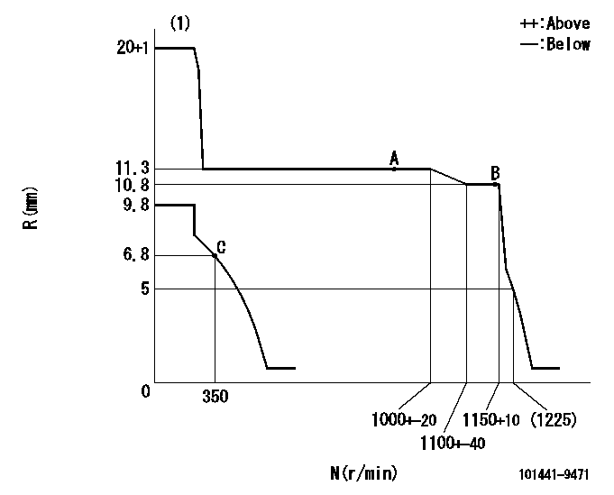
N:Pump speed
R:Rack position (mm)
(1)Notch fixed: K
----------
K=20
----------
----------
K=20
----------
Speed control lever angle
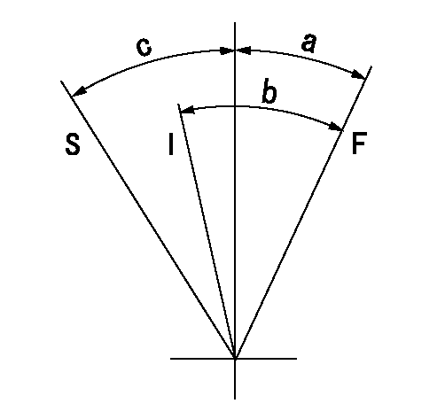
F:Full speed
I:Idle
S:Stop
----------
----------
a=21deg+-5deg b=41deg+-5deg c=32deg+-3deg
----------
----------
a=21deg+-5deg b=41deg+-5deg c=32deg+-3deg
Stop lever angle
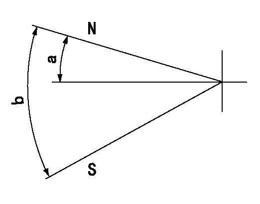
N:Pump normal
S:Stop the pump.
----------
----------
a=19deg+-5deg b=53deg+-5deg
----------
----------
a=19deg+-5deg b=53deg+-5deg
Timing setting
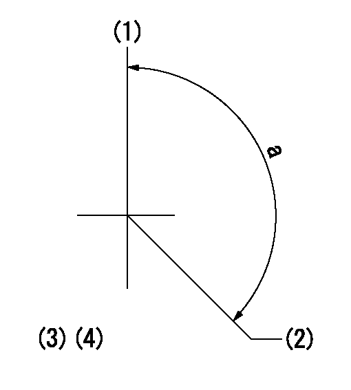
(1)Pump vertical direction
(2)Position of gear mark 'Y' at No 1 cylinder's beginning of injection
(3)B.T.D.C.: aa
(4)-
----------
aa=20deg
----------
a=(130deg)
----------
aa=20deg
----------
a=(130deg)
Information:
Responsibilities of the Oil Company
Performance - The performance of the oil is the responsibility of the oil company. The oil must maintain stable oil control and the oil must control deposits in the combustion chamber and in the crankcase. Engine service life must be maintained at the predicted stage for the particular engine application.Supply - The supply of the oil is the responsibility of the oil company. If special storage and/or shipping is required, the oil company should cover the cost of those items.Oil and fuel analysis - During the evaluation, the oil company should pay for the cost of the oil and fuel analyses. The oil samples should be analyzed by the local Cat dealer in the S O S Services program. The data that is obtained from the oil analyses must be plotted in order to establish trends. The fuel should be analyzed periodically by an independent laboratory. Results of the oil and fuel analyses must be sent to the engine owner. The owner should review the data. Also, the owner should be allowed to keep records of the data.Hardware - If the oil is evaluated in a used engine, two new sets of these components must be installed before the Field Performance Evaluation: pistons, piston rings and cylinder liners. The cost should be covered by the oil company. These new components will be examined as part of the final inspection.Final Inspection - The cost of the final inspection should be paid by the oil company. The costs of additional downtime can also be part of the cost of inspection. If the final inspection reveals severe deposits and/or damage to the hardware, the oil company must make the repairs that are necessary for restoring the engine to an acceptable condition.End of the Evaluation - After completion of the Field Performance Evaluation, the oil company should work with the engine owner in order to restore the engine to normal operation. If the Field Performance Evaluation is not completed, the same conditions should be applicable. The oil company should bear the cost of the restoration. The cost includes the removal of storage tanks, special piping, flow meters, and instrumentation.Final Report - the oil company must prepare a final report that documents the following items:
Initial oil consumption and final oil consumption
The data on oil consumption must be recorded on a minimum schedule of every week. A chart of the data must be included in the final report.
Results of oil analyses
Oil changes
Replacement of oil filters
Results of fuel analyses
Fuel consumption or power output
Average engine speed (rpm)
The typical duty cycle
Close up photographs of the following components from two cylinders must also be included: pistons, piston rings before removal and after removal, piston rings after removal, cylinder liners, crankcase, top deck of the cylinder head, bottom deck of the cylinder head, inlet valves and exhaust valves.The final report should be confidential. The final report should be made available to the engine owner.Responsibilities of the Engine Owner
Engine for the Evaluation - The owner must
