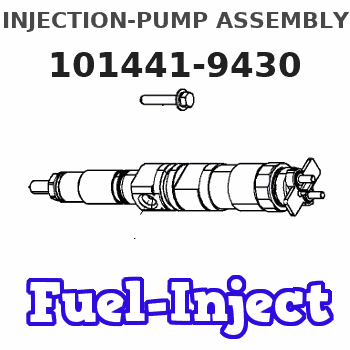
Information injection-pump assembly
BOSCH
9 400 610 076
9400610076
ZEXEL
101441-9430
1014419430
NISSAN-DIESEL
1670039G00
1670039g00
Rating:
Service parts 101441-9430 INJECTION-PUMP ASSEMBLY:
1.
_

6.
COUPLING PLATE
7.
COUPLING PLATE
8.
_
9.
_
11.
Nozzle and Holder
16600-36W00
12.
Open Pre:MPa(Kqf/cm2)
9.8{100}

15.
NOZZLE SET
Include in #1:
101441-9430
as INJECTION-PUMP ASSEMBLY
Include in #2:
105866-4241
as _
Cross reference number
BOSCH
9 400 610 076
9400610076
ZEXEL
101441-9430
1014419430
NISSAN-DIESEL
1670039G00
1670039g00
Zexel num
Bosch num
Firm num
Name
101441-9430
9 400 610 076
1670039G00 NISSAN-DIESEL
INJECTION-PUMP ASSEMBLY
SD25 * K 14BC INJECTION PUMP ASSY PE4A,5A, PE
SD25 * K 14BC INJECTION PUMP ASSY PE4A,5A, PE
Calibration Data:
Adjustment conditions
Test oil
1404 Test oil ISO4113 or {SAEJ967d}
1404 Test oil ISO4113 or {SAEJ967d}
Test oil temperature
degC
40
40
45
Nozzle and nozzle holder
105780-8140
Bosch type code
EF8511/9A
Nozzle
105780-0000
Bosch type code
DN12SD12T
Nozzle holder
105780-2080
Bosch type code
EF8511/9
Opening pressure
MPa
17.2
Opening pressure
kgf/cm2
175
Injection pipe
Outer diameter - inner diameter - length (mm) mm 6-2-600
Outer diameter - inner diameter - length (mm) mm 6-2-600
Tester oil delivery pressure
kPa
157
157
157
Tester oil delivery pressure
kgf/cm2
1.6
1.6
1.6
Direction of rotation (viewed from drive side)
Right R
Right R
Injection timing adjustment
Direction of rotation (viewed from drive side)
Right R
Right R
Injection order
1-3-4-2
Pre-stroke
mm
2.15
2.1
2.2
Beginning of injection position
Drive side NO.1
Drive side NO.1
Difference between angles 1
Cal 1-3 deg. 90 89.5 90.5
Cal 1-3 deg. 90 89.5 90.5
Difference between angles 2
Cal 1-4 deg. 180 179.5 180.5
Cal 1-4 deg. 180 179.5 180.5
Difference between angles 3
Cyl.1-2 deg. 270 269.5 270.5
Cyl.1-2 deg. 270 269.5 270.5
Injection quantity adjustment
Adjusting point
-
Rack position
12.3
Pump speed
r/min
1000
1000
1000
Average injection quantity
mm3/st.
41
40
42
Max. variation between cylinders
%
0
-2.5
2.5
Basic
*
Fixing the rack
*
Injection quantity adjustment_02
Adjusting point
-
Rack position
8.2+-0.5
Pump speed
r/min
300
300
300
Average injection quantity
mm3/st.
8
6.9
9.1
Max. variation between cylinders
%
0
-15
15
Fixing the rack
*
Timer adjustment
Pump speed
r/min
550--
Advance angle
deg.
0
0
0
Remarks
Start
Start
Timer adjustment_02
Pump speed
r/min
500
Advance angle
deg.
0.5
Timer adjustment_03
Pump speed
r/min
800
Advance angle
deg.
0.6
0.1
1.1
Timer adjustment_04
Pump speed
r/min
1200
Advance angle
deg.
2
1.5
2.5
Timer adjustment_05
Pump speed
r/min
1800
Advance angle
deg.
5
4.5
5.5
Timer adjustment_06
Pump speed
r/min
2000
Advance angle
deg.
6
5.5
6.5
Remarks
Finish
Finish
Test data Ex:
Governor adjustment
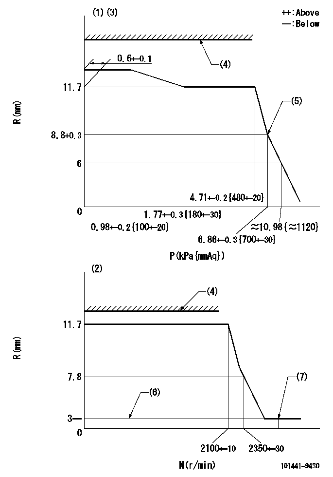
N:Pump speed
R:Rack position (mm)
P:Negative pressure
(1)Pneumatic governor
(2)Mechanical governor
(3)Acting negative pressure: P1
(4)RACK LIMIT: RAL
(5)Beginning of idle sub spring operation: L1
(6)Without stopper disk
(7)Injection quantity Q = Q1 or less (at N = N1)
----------
P1=2.94+-0.2kPa(300+-20mmAq) RAL=14.7-0.3mm L1=8.8+0.3mm Q1=3mm3/st N1=(2600)r/min
----------
----------
P1=2.94+-0.2kPa(300+-20mmAq) RAL=14.7-0.3mm L1=8.8+0.3mm Q1=3mm3/st N1=(2600)r/min
----------
Speed control lever angle
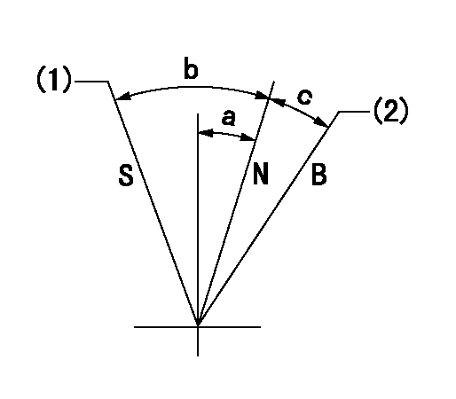
B:When boosted
N:Normal
S:Stop
(1)Rack position = aa
(2)Rack position corresponding to cc
----------
aa=0mm bb=15mm
----------
a=1deg+-5deg b=24deg+-3deg c=5deg+-5deg
----------
aa=0mm bb=15mm
----------
a=1deg+-5deg b=24deg+-3deg c=5deg+-5deg
Timing setting

(1)Pump vertical direction
(2)Position of gear mark 'Y' at No 1 cylinder's beginning of injection
(3)B.T.D.C.: aa
(4)-
----------
aa=18deg
----------
a=(140deg)
----------
aa=18deg
----------
a=(140deg)
Information:
Illustration 17 g03389921
Illustration 18 g03389931
Read the warning and select "Accept" to continue.
Illustration 19 g03389947
Once the reset is completed, a log of the reset is captured and visible as a new row of information in the Diesel Oxidation Catalyst Replacement screen. Selective Catalytic Reduction (SCR) Maintenance on Tier 4 Final Products
Note: Refer to Table 5 for the existing SCR catalyst part number being serviced along with the corresponding new service kit, and the clamp part number required for reassembly.
Table 5
SCR Part Number Service Kit Part Number Required Clamp Part Number
447-8145 N/A 346-0335
447-8143 N/A 346-0335
447-8141 N/A 346-0335
447-8149 N/A 346-0335
447-8147 N/A 346-0335
447-8163 N/A 346-0335
447-8151 N/A 346-0335
375-0989 N/A 346-0335
447-8165 N/A 346-0335
447-8153 N/A 346-0335
447-8161 N/A 346-0335
447-8159 N/A 346-0335
447-8157 N/A 346-0335
447-8169 N/A 346-0335
447-8173 N/A 346-0335
447-8171 N/A 346-0335
447-8167 N/A 346-0335
447-8175 N/A 346-0335 The Aftertreatment SCR Catalyst Replacement procedure must be performed when the SCR Catalyst has been replaced. This is necessary to ensure that the engine meets emissions requirements. Follow the procedure below to reset the SCR Catalyst model in the aftertreatment software.
Connect to Cat® ET.
Illustration 20 g03390636
Connect to "Engine #1 Aftertreatment Controller".
Illustration 21 g03740190
Select "Service" from the top menu and select "Service Procedures".
Illustration 22 g03740205
Select "Aftertreatment #1 SCR Catalyst Replacement" and select "Start".
Illustration 23 g03740210
Select "Reset".
Illustration 24 g03740216
You must read the warning and select "Accept" to continue.
Enter the factory passwords to continue.
Illustration 25 g03740230
Once the reset is completed, a log of the reset is captured and visible as a new row of information in the "Aftertreatment #1 SCR Catalyst Replacement" screen.
Have questions with 101441-9430?
Group cross 101441-9430 ZEXEL
Nissan-Diesel
101441-9430
9 400 610 076
1670039G00
INJECTION-PUMP ASSEMBLY
SD25
SD25