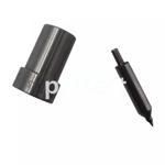
Information injection-pump assembly
BOSCH
F 01G 09U 01J
f01g09u01j
ZEXEL
101441-9390
1014419390
NISSAN-DIESEL
16700T8278
16700t8278
Rating:
Service parts 101441-9390 INJECTION-PUMP ASSEMBLY:
1.
_
6.
COUPLING PLATE
7.
COUPLING PLATE
8.
_
9.
_
11.
Nozzle and Holder
12.
Open Pre:MPa(Kqf/cm2)
9.8(100)
15.
NOZZLE SET
Include in #1:
101441-9390
as INJECTION-PUMP ASSEMBLY
Include in #2:
105866-3220
as _
Cross reference number
BOSCH
F 01G 09U 01J
f01g09u01j
ZEXEL
101441-9390
1014419390
NISSAN-DIESEL
16700T8278
16700t8278
Zexel num
Bosch num
Firm num
Name
Calibration Data:
Adjustment conditions
Test oil
1404 Test oil ISO4113 or {SAEJ967d}
1404 Test oil ISO4113 or {SAEJ967d}
Test oil temperature
degC
40
40
45
Nozzle and nozzle holder
105780-8140
Bosch type code
EF8511/9A
Nozzle
105780-0000
Bosch type code
DN12SD12T
Nozzle holder
105780-2080
Bosch type code
EF8511/9
Opening pressure
MPa
17.2
Opening pressure
kgf/cm2
175
Injection pipe
Outer diameter - inner diameter - length (mm) mm 6-2-600
Outer diameter - inner diameter - length (mm) mm 6-2-600
Tester oil delivery pressure
kPa
157
157
157
Tester oil delivery pressure
kgf/cm2
1.6
1.6
1.6
Direction of rotation (viewed from drive side)
Right R
Right R
Injection timing adjustment
Direction of rotation (viewed from drive side)
Right R
Right R
Injection order
1-3-4-2
Pre-stroke
mm
2.15
2.1
2.2
Beginning of injection position
Drive side NO.1
Drive side NO.1
Difference between angles 1
Cal 1-3 deg. 90 89.5 90.5
Cal 1-3 deg. 90 89.5 90.5
Difference between angles 2
Cal 1-4 deg. 180 179.5 180.5
Cal 1-4 deg. 180 179.5 180.5
Difference between angles 3
Cyl.1-2 deg. 270 269.5 270.5
Cyl.1-2 deg. 270 269.5 270.5
Injection quantity adjustment
Adjusting point
-
Rack position
12.4
Pump speed
r/min
1000
1000
1000
Average injection quantity
mm3/st.
42.1
41.1
43.1
Max. variation between cylinders
%
0
-2.5
2.5
Basic
*
Fixing the rack
*
Injection quantity adjustment_02
Adjusting point
-
Rack position
8.2+-0.5
Pump speed
r/min
300
300
300
Average injection quantity
mm3/st.
8
6.9
9.1
Max. variation between cylinders
%
0
-15
15
Fixing the rack
*
Timer adjustment
Pump speed
r/min
550--
Advance angle
deg.
0
0
0
Remarks
Start
Start
Timer adjustment_02
Pump speed
r/min
500
Advance angle
deg.
0.5
Timer adjustment_03
Pump speed
r/min
800
Advance angle
deg.
0.6
0.1
1.1
Timer adjustment_04
Pump speed
r/min
1200
Advance angle
deg.
2
1.5
2.5
Timer adjustment_05
Pump speed
r/min
1800
Advance angle
deg.
5
4.5
5.5
Timer adjustment_06
Pump speed
r/min
2000
Advance angle
deg.
6
5.5
6.5
Remarks
Finish
Finish
Test data Ex:
Governor adjustment
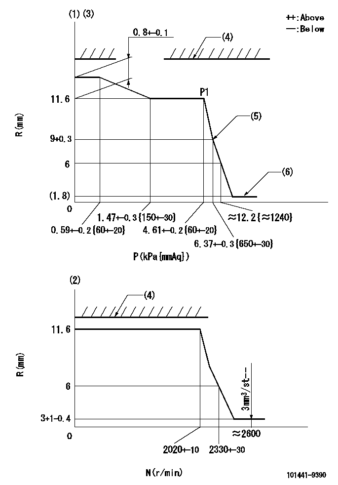
N:Pump speed
R:Rack position (mm)
P:Negative pressure
(1)Pneumatic governor
(2)Mechanical governor
(3)Acting negative pressure: P1
(4)RACK LIMIT: RAL
(5)Beginning of idle sub spring operation: L1
(6)With stopper disk.
----------
RAL=14.7-0.3mm L1=9+0.3mm
----------
----------
RAL=14.7-0.3mm L1=9+0.3mm
----------
Speed control lever angle
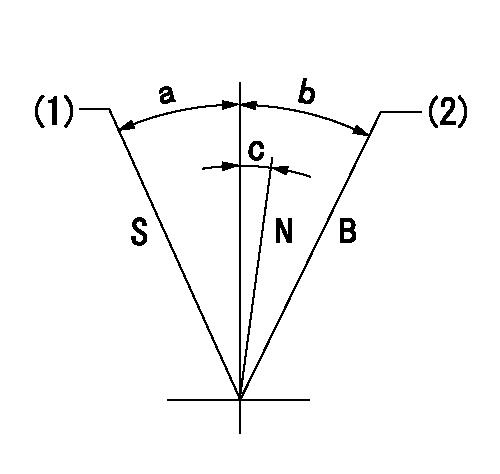
N:Normal
B:When boosted
S:Stop
(1)Rack position = aa
(2)Rack position corresponding to cc
----------
aa=(1.8)mm bb=15mm
----------
a=20deg+-3deg b=6deg+-5deg c=0deg+-5deg
----------
aa=(1.8)mm bb=15mm
----------
a=20deg+-3deg b=6deg+-5deg c=0deg+-5deg
Timing setting
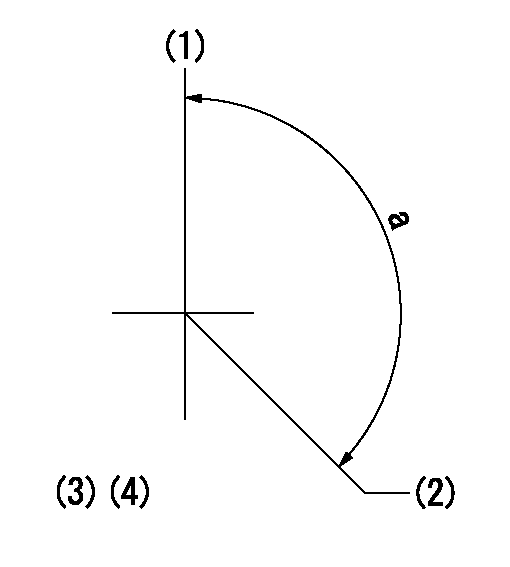
(1)Pump vertical direction
(2)Position of gear mark 'Y' at No 1 cylinder's beginning of injection
(3)B.T.D.C.: aa
(4)-
----------
aa=18deg
----------
a=(140deg)
----------
aa=18deg
----------
a=(140deg)
Information:
Filtering of the Fuel
The quality of the fuel is an important consideration for maintenance of the fuel filters. A poor quality of fuel can reduce the service life of the fuel filter elements by 50 percent or more. To increase the service life of fuel filter elements, use a good quality of fuel. Monitor the readings of the fuel gauges and service the fuel filters at the recommended intervals.The secondary fuel filters that are supplied by Cat are mounted remotely from the engine. The filters are installed in the fuel supply line directly before the engine.
For heavy fuel oil with a viscosity of 40 cSt at 50 °C (122 °F), the viscosity of the fuel must be reduced prior to the fuel filters. This will allow fuel to pass through the filter elements without causing the elements to collapse. Reduce the viscosity to a range that is between 15 and 20 cSt at 50 °C (122 °F).
Overheating the fuel or the fuel filter can result in personal injury and/or damage to the engine. Use extreme care and caution for heating of the fuel filter.
Heating of the fuel filter will enable the viscosity to be reduced. The fuel temperature and warm-up time depend on the type of fuel and installation.
The viscosity of the fuel at the engine must be between 10 cSt and 20cSt. The temperature of the fuel at the engine must not exceed 135 °C (275 °F).
Heating of the Fuel
Precise temperature control of heavy fuel oil is critical for the most complete combustion, centrifugal cleaning, and settling of contaminants. If the temperature is not properly controlled, sludge and vapors can form. This material inhibits the treatment of the fuel. Also, combustion of the fuel is reduced. The result is a reduction of the service life of the fuel system components and the engine.Note: The temperatures that are required for controlling sludge and vapor mainly depend on the fuel quality. An analysis of the fuel is necessary to determine the proper temperature for both treatment and viscosity.The following parameters can be used as initial indications of improper temperature control:
Variation of the exhaust port temperatures
Viscosity of the fuel
Knocking
Fuel temperature
Opacity of the exhaust smokeUse the jacket water heaters before starting an engine with heavy fuel oil. Use of the jacket water heaters will reduce the viscosity of the fuel in the fuel injectors. Startability will be improved.Table 5 lists the jacket water temperatures that are appropriate for different fuel viscosities.
Table 5
Fuel Viscosity and Jacket Water Temperature
Fuel Viscosity Jacket Water Temperature
Less than 40 cSt at 50 °C (122 °F) 45 °C (113 °F)
More than 40 cSt at 50 °C (122 °F) 65 °C (149 °F) Normally, deactivate the jacket water heaters after the engine has started.Analysis of Heavy Fuel Oil
Caterpillar Inc. does not provide analyses of heavy fuel oil. Chemical labs throughout the world can evaluate fuel properties on a regular basis. Analyses of heavy fuel oil may also be obtained from these organizations: independent testing laboratories, oil companies
