Information injection-pump assembly
ZEXEL
101441-9360
1014419360
NISSAN-DIESEL
16700J1801
16700j1801

Rating:
Service parts 101441-9360 INJECTION-PUMP ASSEMBLY:
1.
_

6.
COUPLING PLATE
7.
COUPLING PLATE
8.
_
9.
_
11.
Nozzle and Holder
16600-36W00
12.
Open Pre:MPa(Kqf/cm2)
9.8{100}

15.
NOZZLE SET
Include in #1:
101441-9360
as INJECTION-PUMP ASSEMBLY
Include in #2:
105856-3250
as _
Cross reference number
ZEXEL
101441-9360
1014419360
NISSAN-DIESEL
16700J1801
16700j1801
Zexel num
Bosch num
Firm num
Name
101441-9360
16700J1801 NISSAN-DIESEL
INJECTION-PUMP ASSEMBLY
SD25 * K
SD25 * K
Calibration Data:
Adjustment conditions
Test oil
1404 Test oil ISO4113 or {SAEJ967d}
1404 Test oil ISO4113 or {SAEJ967d}
Test oil temperature
degC
40
40
45
Nozzle and nozzle holder
105780-8140
Bosch type code
EF8511/9A
Nozzle
105780-0000
Bosch type code
DN12SD12T
Nozzle holder
105780-2080
Bosch type code
EF8511/9
Opening pressure
MPa
17.2
Opening pressure
kgf/cm2
175
Injection pipe
Outer diameter - inner diameter - length (mm) mm 6-2-600
Outer diameter - inner diameter - length (mm) mm 6-2-600
Tester oil delivery pressure
kPa
157
157
157
Tester oil delivery pressure
kgf/cm2
1.6
1.6
1.6
Direction of rotation (viewed from drive side)
Right R
Right R
Injection timing adjustment
Direction of rotation (viewed from drive side)
Right R
Right R
Injection order
1-3-4-2
Pre-stroke
mm
2.15
2.1
2.2
Beginning of injection position
Drive side NO.1
Drive side NO.1
Difference between angles 1
Cal 1-3 deg. 90 89.5 90.5
Cal 1-3 deg. 90 89.5 90.5
Difference between angles 2
Cal 1-4 deg. 180 179.5 180.5
Cal 1-4 deg. 180 179.5 180.5
Difference between angles 3
Cyl.1-2 deg. 270 269.5 270.5
Cyl.1-2 deg. 270 269.5 270.5
Injection quantity adjustment
Adjusting point
-
Rack position
12.3
Pump speed
r/min
1000
1000
1000
Average injection quantity
mm3/st.
41
40
42
Max. variation between cylinders
%
0
-2.5
2.5
Basic
*
Fixing the rack
*
Injection quantity adjustment_02
Adjusting point
-
Rack position
8.2+-0.5
Pump speed
r/min
300
300
300
Average injection quantity
mm3/st.
8
6.9
9.1
Max. variation between cylinders
%
0
-15
15
Fixing the rack
*
Timer adjustment
Pump speed
r/min
550--
Advance angle
deg.
0
0
0
Remarks
Start
Start
Timer adjustment_02
Pump speed
r/min
500
Advance angle
deg.
0.5
Timer adjustment_03
Pump speed
r/min
800
Advance angle
deg.
0.6
0.1
1.1
Timer adjustment_04
Pump speed
r/min
1200
Advance angle
deg.
2
1.5
2.5
Timer adjustment_05
Pump speed
r/min
1800
Advance angle
deg.
5
4.5
5.5
Timer adjustment_06
Pump speed
r/min
2000
Advance angle
deg.
6
5.5
6.5
Remarks
Finish
Finish
Test data Ex:
Governor adjustment
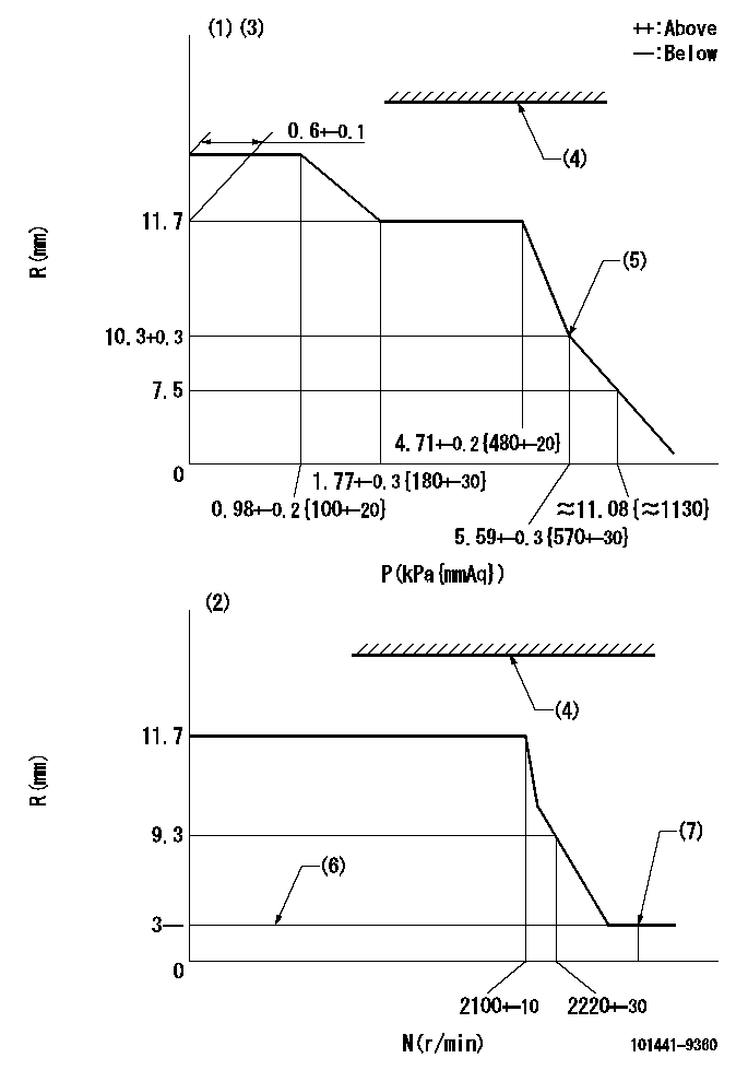
N:Pump speed
R:Rack position (mm)
P:Negative pressure
(1)Pneumatic governor
(2)Mechanical governor
(3)Acting negative pressure: P1
(4)RACK LIMIT: RAL
(5)Beginning of idle sub spring operation: L1
(6)Without stopper disk
(7)Injection quantity Q = Q1 or less (at N = N1)
----------
P1=2.94+-0.2kPa(300+-20mmAq) RAL=14.7-0.3mm L1=10.3+0.3mm Q1=3mm3/st N1=(2600)r/min
----------
----------
P1=2.94+-0.2kPa(300+-20mmAq) RAL=14.7-0.3mm L1=10.3+0.3mm Q1=3mm3/st N1=(2600)r/min
----------
Speed control lever angle
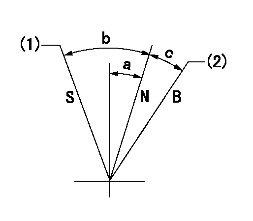
B:When boosted
N:Normal
S:Stop
(1)Rack position = aa
(2)Rack position corresponding to cc
----------
aa=0mm bb=15mm
----------
a=1deg+-5deg b=24deg+-3deg c=5deg+-5deg
----------
aa=0mm bb=15mm
----------
a=1deg+-5deg b=24deg+-3deg c=5deg+-5deg
0000001501 ACS
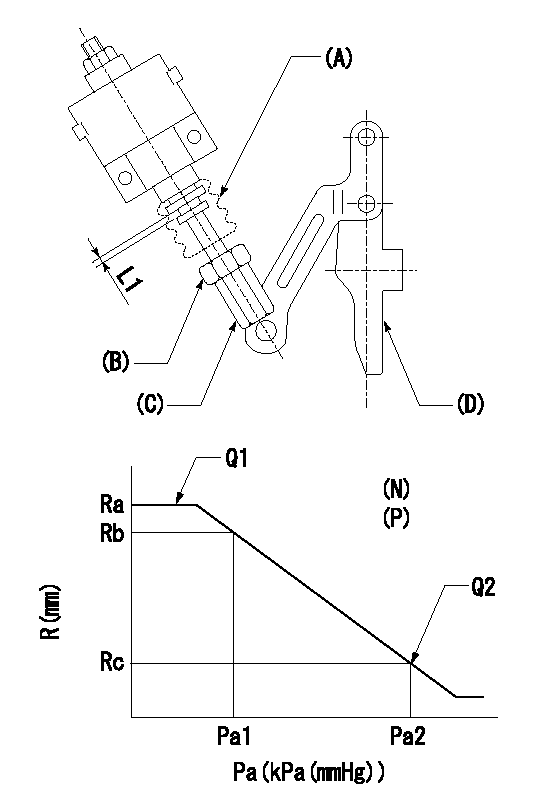
(N): Speed of the pump
(P): governor's negative pressure
(Pa): aneroid compensator's negative pressure
(A) rubber boot
(B) Nut
(c) Nut
(D) Lever
1. Aneroid compensator installation
(1)Turn nut (C) to adjust gap to L1. (Remove rubber boot at adjustment.)
(2)Lock using nut (B).
(3)After installation, the lever D must move smoothly when the lever D is moved to the excess fuel side, and R = R1 or more.
----------
L1=0.1~0.5mm R1=17mm
----------
N=1000r/min P=0.5kPa(50mmAq) Ra=12.3mm Rb=12.25mm Rc=11.85+-0.2mm Pa1=8-5.3kPa(60-40mmHg) Pa2=16.7kPa(125mmHg) Q1=- Q2=-
----------
L1=0.1~0.5mm R1=17mm
----------
N=1000r/min P=0.5kPa(50mmAq) Ra=12.3mm Rb=12.25mm Rc=11.85+-0.2mm Pa1=8-5.3kPa(60-40mmHg) Pa2=16.7kPa(125mmHg) Q1=- Q2=-
Timing setting

(1)Pump vertical direction
(2)Position of gear mark 'Y' at No 1 cylinder's beginning of injection
(3)B.T.D.C.: aa
(4)-
----------
aa=18deg
----------
a=(140deg)
----------
aa=18deg
----------
a=(140deg)
Information:
General Recommendations and Contamination Control Guidelines for Fuels
Follow all applicable industry standards and all applicable governmental, environmental, and safety guidelines, practices, regulations, and mandates.Note: These general recommendations and guidelines concerning maintenance and care of fuel and fuel storage systems are not intended to be all inclusive. Discuss proper fuel safety and health, handling, and maintenance practices with your fuel supplier. Use of these general recommendations and guidelines does not lessen the engine owners and/or fuel supplier responsibility to follow all industry standard practices for fuel storage and for fuel handling.Note: Where recommendations for draining water and/or sediment and/or debris are stated, dispose of this waste according to all applicable regulations and mandates.Note: Caterpillar filters are designed and built to provide optimal performance and protection of the fuel system components.Clean fuels, as detailed below, are strongly recommended to allow optimal performance and durability of the fuel systems and to reduce power loss, failures, and related down time of engines.Fuels of “ISO 18/16/13” cleanliness levels or cleaner as dispensed into the engine or machine fuel tank should be used. Reduced power, failures and related downtime can result if clean fuels are not used. Fuels of “ISO 18/16/13” are particularly important for new fuel system designs such as Common Rail injection systems and unit injection systems. These new injection system designs utilize higher fuel pressures and are designed with tight clearances between moving parts to meet required stringent emissions regulations. Peak injection pressures in current fuel injection systems may exceed 30,000 psi. Clearances in these systems are less than 5 µm. As a result, particle contaminants as small as 4 µm can cause scoring and scratching of internal pump and injector surfaces and of injector nozzles.Water in the fuel causes cavitation, corrosion of fuel system parts, and provides an environment where microbial growth in the fuel can flourish. Other sources of fuel contamination are soaps, gels, or other compounds that may result from undesirable chemical interactions in the fuels. Gels and other insoluble compounds can also form in biodiesel fuel at low temperatures or if biodiesel is stored for extended periods. An indication of microbial contamination, detrimental fuel additives interactions, or cold temperature gel is very rapid filter plugging of bulk fuel filters or machine fuel filters.To reduce downtime due to contamination, follow these fuel maintenance guidelines in addition to the recommendations given in the "Contamination Control" Chapter in this Special Publication:
Use high-quality fuels per recommended and required specifications (refer to the “Fuel” chapter in this Special Publication).
Do not add new engine oil, waste engine oil or any oil product to the fuel unless the engine is designed and certified to burn diesel engine oil (for example Caterpillar ORS designed for large engines). Engine oils may raise the sulfur level of the fuel and may cause fouling of the fuel system and loss of performance. Engine oils in fuels can also reduce the maintenance intervals of aftertreatment devices in Tier 4 machines.
Use recommended Cat filtration products, including Cat Advanced Efficiency Fuel
Have questions with 101441-9360?
Group cross 101441-9360 ZEXEL
Nissan-Diesel
101441-9360
16700J1801
INJECTION-PUMP ASSEMBLY
SD25
SD25