Information injection-pump assembly
ZEXEL
101441-9332
1014419332
NISSAN-DIESEL
16700V6604
16700v6604

Rating:
Cross reference number
ZEXEL
101441-9332
1014419332
NISSAN-DIESEL
16700V6604
16700v6604
Zexel num
Bosch num
Firm num
Name
Calibration Data:
Adjustment conditions
Test oil
1404 Test oil ISO4113 or {SAEJ967d}
1404 Test oil ISO4113 or {SAEJ967d}
Test oil temperature
degC
40
40
45
Nozzle and nozzle holder
105780-8140
Bosch type code
EF8511/9A
Nozzle
105780-0000
Bosch type code
DN12SD12T
Nozzle holder
105780-2080
Bosch type code
EF8511/9
Opening pressure
MPa
17.2
Opening pressure
kgf/cm2
175
Injection pipe
Outer diameter - inner diameter - length (mm) mm 6-2-600
Outer diameter - inner diameter - length (mm) mm 6-2-600
Tester oil delivery pressure
kPa
157
157
157
Tester oil delivery pressure
kgf/cm2
1.6
1.6
1.6
Direction of rotation (viewed from drive side)
Right R
Right R
Injection timing adjustment
Direction of rotation (viewed from drive side)
Right R
Right R
Injection order
1-3-4-2
Pre-stroke
mm
2.3
2.25
2.35
Beginning of injection position
Drive side NO.1
Drive side NO.1
Difference between angles 1
Cal 1-3 deg. 90 89.5 90.5
Cal 1-3 deg. 90 89.5 90.5
Difference between angles 2
Cal 1-4 deg. 180 179.5 180.5
Cal 1-4 deg. 180 179.5 180.5
Difference between angles 3
Cyl.1-2 deg. 270 269.5 270.5
Cyl.1-2 deg. 270 269.5 270.5
Injection quantity adjustment
Adjusting point
-
Rack position
11.5
Pump speed
r/min
850
850
850
Average injection quantity
mm3/st.
32.6
31.6
33.6
Max. variation between cylinders
%
0
-2.5
2.5
Basic
*
Fixing the rack
*
Injection quantity adjustment_02
Adjusting point
-
Rack position
8.4+-0.5
Pump speed
r/min
300
300
300
Average injection quantity
mm3/st.
8
6.9
9.1
Max. variation between cylinders
%
0
-15
15
Fixing the rack
*
Timer adjustment
Pump speed
r/min
550--
Advance angle
deg.
0
0
0
Remarks
Start
Start
Timer adjustment_02
Pump speed
r/min
500
Advance angle
deg.
0.5
Timer adjustment_03
Pump speed
r/min
1200
Advance angle
deg.
2
1.5
2.5
Timer adjustment_04
Pump speed
r/min
2150
Advance angle
deg.
7
6.5
7.5
Remarks
Finish
Finish
Test data Ex:
Governor adjustment
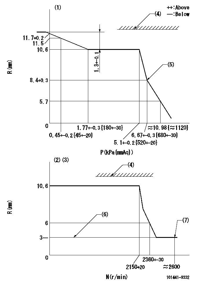
N:Pump speed
R:Rack position (mm)
P:Negative pressure
(1)Pneumatic governor
(2)Mechanical governor
(3)Acting negative pressure: P1
(4)RACK LIMIT: RAL
(5)Beginning of idle sub spring operation: L1
(6)Without stopper disk
(7)Injection quantity Q = Q1 or less
----------
P1=2.55+-0.2kPa(260+-20mmAq) RAL=12.1+0.2mm L1=8.4+0.3mm Q1=3mm3/st
----------
----------
P1=2.55+-0.2kPa(260+-20mmAq) RAL=12.1+0.2mm L1=8.4+0.3mm Q1=3mm3/st
----------
0000001101
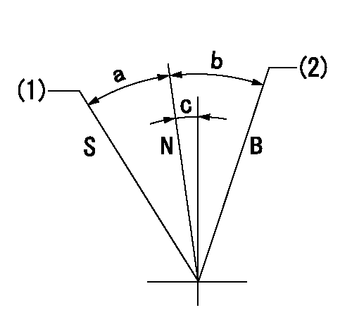
N:Normal
B:When boosted
S:Stop
(1)Rack position = aa
(2)Rack position corresponding to cc
----------
aa=0mm bb=15mm
----------
a=24deg+-3deg b=6deg+-5deg c=1.5deg+-5deg
----------
aa=0mm bb=15mm
----------
a=24deg+-3deg b=6deg+-5deg c=1.5deg+-5deg
Timing setting

(1)Pump vertical direction
(2)Position of gear mark 'Y' at No 1 cylinder's beginning of injection
(3)B.T.D.C.: aa
(4)-
----------
aa=18deg
----------
a=(130deg)
----------
aa=18deg
----------
a=(130deg)
Information:
Introduction
This Special Instruction contains the strap torquing procedure for the straps on the DEF tank.Read the entire Special Instruction. Understand the information before you perform any procedures. Strap Torquing Procedure
Illustration 1 g03354750
(1) Strap (2) Nut
Install strap (1) and torque nut (2) .Torque for nut (2) ... 11 1 N m (97 9 lb in)Note: If the strap has a hook or other non-adjustable fastener on one end, only the adjustment end is torqued during installation.Note: If both ends of the strap have adjustable fasteners, both ends should be torqued only once. Do not go back and forth when applying assembly torque. Torque the first side to specification, then ensure that the torque on the second side is at specifications. Do not go back and retorque the first side.