Information injection-pump assembly
BOSCH
9 400 614 137
9400614137
ZEXEL
101441-9292
1014419292
NISSAN-DIESEL
16700V6603
16700v6603

Rating:
Service parts 101441-9292 INJECTION-PUMP ASSEMBLY:
1.
_

6.
COUPLING PLATE
7.
COUPLING PLATE
8.
_
9.
_
11.
Nozzle and Holder
16600-36W00
12.
Open Pre:MPa(Kqf/cm2)
9.8{100}

15.
NOZZLE SET
Include in #1:
101441-9292
as INJECTION-PUMP ASSEMBLY
Include in #2:
105856-7143
as _
Cross reference number
BOSCH
9 400 614 137
9400614137
ZEXEL
101441-9292
1014419292
NISSAN-DIESEL
16700V6603
16700v6603
Zexel num
Bosch num
Firm num
Name
101441-9292
9 400 614 137
16700V6603 NISSAN-DIESEL
INJECTION-PUMP ASSEMBLY
SD23 * K 14BC INJECTION PUMP ASSY PE4A,5A, PE
SD23 * K 14BC INJECTION PUMP ASSY PE4A,5A, PE
Calibration Data:
Adjustment conditions
Test oil
1404 Test oil ISO4113 or {SAEJ967d}
1404 Test oil ISO4113 or {SAEJ967d}
Test oil temperature
degC
40
40
45
Nozzle and nozzle holder
105780-8140
Bosch type code
EF8511/9A
Nozzle
105780-0000
Bosch type code
DN12SD12T
Nozzle holder
105780-2080
Bosch type code
EF8511/9
Opening pressure
MPa
17.2
Opening pressure
kgf/cm2
175
Injection pipe
Outer diameter - inner diameter - length (mm) mm 6-2-600
Outer diameter - inner diameter - length (mm) mm 6-2-600
Tester oil delivery pressure
kPa
157
157
157
Tester oil delivery pressure
kgf/cm2
1.6
1.6
1.6
Direction of rotation (viewed from drive side)
Right R
Right R
Injection timing adjustment
Direction of rotation (viewed from drive side)
Right R
Right R
Injection order
1-3-4-2
Pre-stroke
mm
2.3
2.25
2.35
Beginning of injection position
Drive side NO.1
Drive side NO.1
Difference between angles 1
Cal 1-3 deg. 90 89.5 90.5
Cal 1-3 deg. 90 89.5 90.5
Difference between angles 2
Cal 1-4 deg. 180 179.5 180.5
Cal 1-4 deg. 180 179.5 180.5
Difference between angles 3
Cyl.1-2 deg. 270 269.5 270.5
Cyl.1-2 deg. 270 269.5 270.5
Injection quantity adjustment
Adjusting point
-
Rack position
11.5
Pump speed
r/min
1000
1000
1000
Average injection quantity
mm3/st.
36.1
35.1
37.1
Max. variation between cylinders
%
0
-2.5
2.5
Basic
*
Fixing the rack
*
Injection quantity adjustment_02
Adjusting point
-
Rack position
8.1+-0.5
Pump speed
r/min
300
300
300
Average injection quantity
mm3/st.
8
6.9
9.1
Max. variation between cylinders
%
0
-15
15
Fixing the rack
*
Injection quantity adjustment_03
Adjusting point
-
Rack position
-
Pump speed
r/min
1000
1000
1000
Average injection quantity
mm3/st.
36.1
35.6
36.6
Remarks
Set full load.
Set full load.
Timer adjustment
Pump speed
r/min
550--
Advance angle
deg.
0
0
0
Remarks
Start
Start
Timer adjustment_02
Pump speed
r/min
500
Advance angle
deg.
0.5
Timer adjustment_03
Pump speed
r/min
1200
Advance angle
deg.
2
1.5
2.5
Timer adjustment_04
Pump speed
r/min
2150
Advance angle
deg.
7
6.5
7.5
Remarks
Finish
Finish
Test data Ex:
Governor adjustment
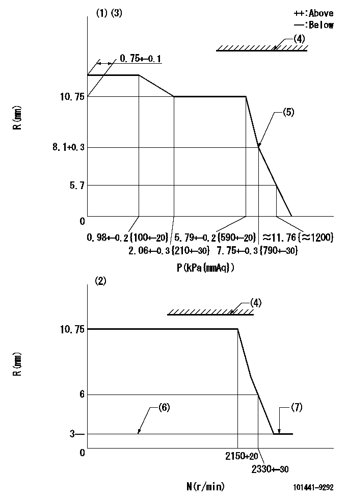
N:Pump speed
R:Rack position (mm)
P:Negative pressure
(1)Pneumatic governor
(2)Mechanical governor
(3)Acting negative pressure: P1
(4)RACK LIMIT: RAL
(5)Beginning of idle sub spring operation: L1
(6)Without stopper disk
(7)Injection quantity Q = Q1 or less (at N = N1)
----------
P1=2.55+-0.2kPa(260+-20)mmAq RAL=14.7-0.3mm L1=8.1+0.3mm Q1=3mm3/st N1=(2600)r/min
----------
----------
P1=2.55+-0.2kPa(260+-20)mmAq RAL=14.7-0.3mm L1=8.1+0.3mm Q1=3mm3/st N1=(2600)r/min
----------
Speed control lever angle
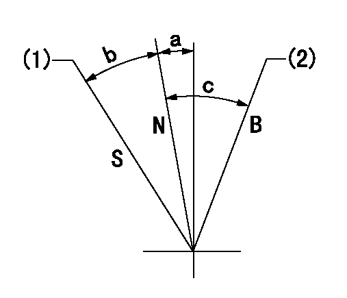
N:Normal
B:When boosted
S:Stop
(1)Rack position = aa
(2)Rack position corresponding to cc
----------
aa=0mm bb=15mm
----------
a=2.5deg+-5deg b=23deg+-3deg c=7deg+-5deg
----------
aa=0mm bb=15mm
----------
a=2.5deg+-5deg b=23deg+-3deg c=7deg+-5deg
0000001501 ACS
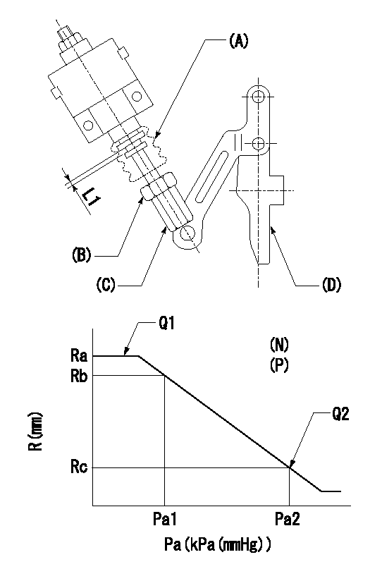
(N): Speed of the pump
(P): governor's negative pressure
(Pa): aneroid compensator's negative pressure
(A) rubber boot
(B) Nut
(c) Nut
(D) Lever
1. Aneroid compensator installation
(1)Turn nut (C) to adjust gap to L1. (Remove rubber boot at adjustment.)
(2)Lock using nut (B).
(3)After installation, the lever D must move smoothly when the lever D is moved to the excess fuel side, and R = R1 or more.
----------
L1=0.1~0.5mm R1=16mm
----------
N=1000r/min P=0.4kPa(40mmAq) Ra=11.5mm Rb=11.45mm Rc=11.05+-0.2mm Pa1=8-5.3kPa(60-40mmHg) Pa2=16.7kPa(125mmHg) Q1=- Q2=-
----------
L1=0.1~0.5mm R1=16mm
----------
N=1000r/min P=0.4kPa(40mmAq) Ra=11.5mm Rb=11.45mm Rc=11.05+-0.2mm Pa1=8-5.3kPa(60-40mmHg) Pa2=16.7kPa(125mmHg) Q1=- Q2=-
Timing setting

(1)Pump vertical direction
(2)Position of gear mark 'Y' at No 1 cylinder's beginning of injection
(3)B.T.D.C.: aa
(4)-
----------
aa=18deg
----------
a=(130deg)
----------
aa=18deg
----------
a=(130deg)
Information:
Illustration 8 g00778880
This is an illustration of the 154-8016 Fuel Injector Seals . (14) Metal Seal (15) 133-3715 Backup Ring (16) 150-4105 Backup Ring (17) 9X-7557 O-Ring Seal (18) 148-2903 O-Ring Seal (19) 149-5240 Backup Ring (20) 109-3207 O-Ring Seal
Illustration 9 g00638512
(A) 149-2955 Seal Protector
Illustration 10 g00638506
(B) 149-2956 Seal Installer
The correct procedures and tooling specifications must always be used. Failure to follow any of the procedures may result in damage, malfunction, or possible engine failure.
Note: Install the upper seal pack first. Then install the middle seal pack. Finally, install the bottom O-Ring Seal.
Both the 149-2955 Seal Protector (A) and the 149-2956 Seal Installer (B) should be used when you are installing the upper high pressure seals.Note: New seals should be installed after each removal of the injector from the engine.
Lubricate the O-Ring seals and the sleeve bore of the injector sparingly with clean engine oil.Note: Proper installation of the injector is very important. Damage to the upper high pressure seals can cause excessive oil leakage under the valve cover. This may cause the engine not to start due to a low actuation pressure. Damage to the lower high pressure seals may allow high pressure oil to leak into the fuel supply passage. This will result in excessive oil consumption.
Illustration 11 g00621566
(X) 8T-2396 Bolts . (Y) 159-0288 Deflector . Note: Some of these engines were built without the 159-0288 Deflector . During the installation of the unit injectors, the deflectors should be installed. Six 159-0288 Deflectors and six 8T-2396 Bolts are required for each engine. These new deflectors and bolts replace the former 6V-8653 Bolts .
Illustration 12 g00294210
Illustration 13 g00312124
(C) 152-1057 Fuel Injector Installer
Carefully install the injector into the injector bore. If access permits you to seat the injector, push the injector straight down on top of the injector's solenoid by hand until the injector is firmly seated in the injector bore. Pushing hard enough to compress the injector's seals may be difficult. If the injector can not be seated by hand, use a 152-1057 Fuel Injector Installer (C). Note: Do NOT pry on the top of the injector with another tool. Do NOT strike the injector with a hammer. Damage to the injector will result. Damage to the injector that is due to improper installation is not a warrantable failure.
Illustration 14 g00778888
(2) Wiring Harness Connection (3) Clamp (10) Shoulder Bolt (11) Socket Head BoltNote: Do not use the shoulder bolt and the socket head bolt in order to seat the injector. If a side load is placed on the bolts, the bolts may fail.
After the injector is seated, position the clamp (2) and tighten the Shoulder Bolt (10) to a torque of 6 N m (50 lb in). Then tighten the Socket Head Bolt (11) to a torque of 12 N m (9 lb ft).
Insert the harness connectors (2) back into the injectors' solenoids. Ensure that the clips are snapped back into
Have questions with 101441-9292?
Group cross 101441-9292 ZEXEL
Nissan-Diesel
101441-9292
9 400 614 137
16700V6603
INJECTION-PUMP ASSEMBLY
SD23
SD23