Information injection-pump assembly
BOSCH
9 400 619 750
9400619750
ZEXEL
101441-9110
1014419110
NISSAN-DIESEL
1671290070
1671290070
Rating:
Service parts 101441-9110 INJECTION-PUMP ASSEMBLY:
1.
_
6.
COUPLING PLATE
7.
COUPLING PLATE
8.
_
9.
_
10.
NOZZLE AND HOLDER ASSY
11.
Nozzle and Holder
12.
Open Pre:MPa(Kqf/cm2)
9.8{100}
15.
NOZZLE SET
Include in #1:
101441-9110
as INJECTION-PUMP ASSEMBLY
Include in #2:
105856-2483
as _
Cross reference number
BOSCH
9 400 619 750
9400619750
ZEXEL
101441-9110
1014419110
NISSAN-DIESEL
1671290070
1671290070
Zexel num
Bosch num
Firm num
Name
101441-9110
9 400 619 750
1671290070 NISSAN-DIESEL
INJECTION-PUMP ASSEMBLY
SD25 * K
SD25 * K
Calibration Data:
Adjustment conditions
Test oil
1404 Test oil ISO4113 or {SAEJ967d}
1404 Test oil ISO4113 or {SAEJ967d}
Test oil temperature
degC
40
40
45
Nozzle and nozzle holder
105780-8140
Bosch type code
EF8511/9A
Nozzle
105780-0000
Bosch type code
DN12SD12T
Nozzle holder
105780-2080
Bosch type code
EF8511/9
Opening pressure
MPa
17.2
Opening pressure
kgf/cm2
175
Injection pipe
Outer diameter - inner diameter - length (mm) mm 6-2-600
Outer diameter - inner diameter - length (mm) mm 6-2-600
Tester oil delivery pressure
kPa
157
157
157
Tester oil delivery pressure
kgf/cm2
1.6
1.6
1.6
Direction of rotation (viewed from drive side)
Right R
Right R
Injection timing adjustment
Direction of rotation (viewed from drive side)
Right R
Right R
Injection order
1-3-4-2
Pre-stroke
mm
2.3
2.25
2.35
Beginning of injection position
Drive side NO.1
Drive side NO.1
Difference between angles 1
Cal 1-3 deg. 90 89.5 90.5
Cal 1-3 deg. 90 89.5 90.5
Difference between angles 2
Cal 1-4 deg. 180 179.5 180.5
Cal 1-4 deg. 180 179.5 180.5
Difference between angles 3
Cyl.1-2 deg. 270 269.5 270.5
Cyl.1-2 deg. 270 269.5 270.5
Injection quantity adjustment
Adjusting point
A
Rack position
10.3
Pump speed
r/min
1500
1500
1500
Average injection quantity
mm3/st.
40.2
39.2
41.2
Max. variation between cylinders
%
0
-2.5
2.5
Basic
*
Fixing the lever
*
Injection quantity adjustment_02
Adjusting point
B
Rack position
9.7
Pump speed
r/min
1500
1500
1500
Average injection quantity
mm3/st.
36
34.5
37.5
Max. variation between cylinders
%
0
-4
4
Fixing the rack
*
Injection quantity adjustment_03
Adjusting point
C
Rack position
6.8+-0.5
Pump speed
r/min
350
350
350
Average injection quantity
mm3/st.
8.6
7.5
9.7
Max. variation between cylinders
%
0
-15
15
Fixing the rack
*
Timer adjustment
Pump speed
r/min
550--
Advance angle
deg.
0
0
0
Remarks
Start
Start
Timer adjustment_02
Pump speed
r/min
500
Advance angle
deg.
0.5
Timer adjustment_03
Pump speed
r/min
900
Advance angle
deg.
1.8
1.3
2.3
Timer adjustment_04
Pump speed
r/min
1200
Advance angle
deg.
3.3
2.8
3.8
Timer adjustment_05
Pump speed
r/min
1500
Advance angle
deg.
5
4.5
5.5
Remarks
Finish
Finish
Test data Ex:
Governor adjustment
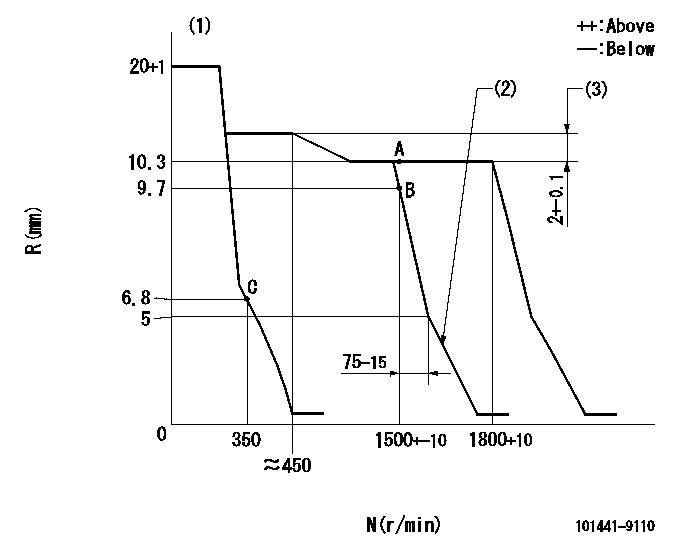
N:Pump speed
R:Rack position (mm)
(1)Target notch: K
(2)Idle sub spring setting: L1.
(3)Rack difference between N = N1 and N = N2
----------
K=16 L1=5-0.5mm N1=1450r/min N2=400r/min
----------
----------
K=16 L1=5-0.5mm N1=1450r/min N2=400r/min
----------
Speed control lever angle
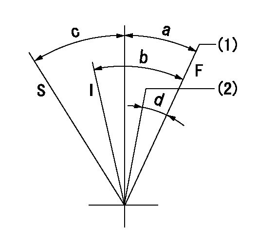
F:Full speed
I:Idle
S:Stop
(1)Set the pump speed at aa. (At delivery)
(2)Pump speed = bb
----------
aa=1800r/min bb=1500r/min
----------
a=27deg+-5deg b=37deg+-5deg c=32deg+-3deg d=7deg+-5deg
----------
aa=1800r/min bb=1500r/min
----------
a=27deg+-5deg b=37deg+-5deg c=32deg+-3deg d=7deg+-5deg
Stop lever angle
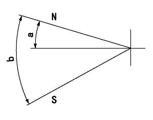
N:Pump normal
S:Stop the pump.
----------
----------
a=19deg+-5deg b=53deg+-5deg
----------
----------
a=19deg+-5deg b=53deg+-5deg
0000001501 GOV FULL LOAD ADJUSTMENT
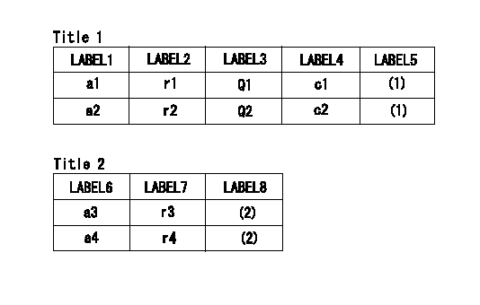
Title1:Full load stopper adjustment
Title2:Governor set speed
LABEL1:Distinguishing
LABEL2:Pump speed (r/min)
LABEL3:Ave. injection quantity (mm3/st)
LABEL4:Max. var. bet. cyl.
LABEL5:Remarks
LABEL6:Distinguishing
LABEL7:Governor set speed (r/min)
LABEL8:Remarks
(1)Adjustment conditions are the same as those for measuring injection quantity.
(2)-
----------
----------
a1=B a2=- r1=1500r/min r2=- Q1=40.2+-1mm3/st Q2=- c1=+-2.5% c2=- a3=36 a4=30 r3=1800r/min r4=1500r/min
----------
----------
a1=B a2=- r1=1500r/min r2=- Q1=40.2+-1mm3/st Q2=- c1=+-2.5% c2=- a3=36 a4=30 r3=1800r/min r4=1500r/min
Timing setting
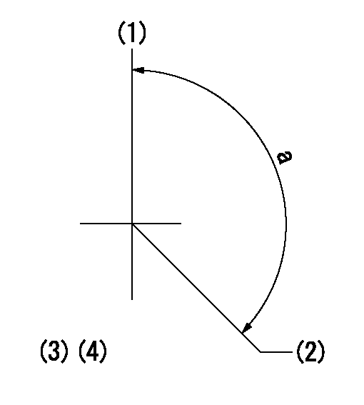
(1)Pump vertical direction
(2)Position of gear mark 'Y' at No 1 cylinder's beginning of injection
(3)B.T.D.C.: aa
(4)-
----------
aa=20deg
----------
a=(130deg)
----------
aa=20deg
----------
a=(130deg)
Information:
CONFIDENTIAL
TECHNICAL INFORMATION BULLETIN November 21, 2001
Generator Set PM3516 (BPD)
Component Code(s) 7060SUBJECT: XQ 2000 Power Module Slide Rail on 3500B Diesel Generator Sets
PROBLEM:
The 141-6413 Rail Group - Slide was used to facilitate the correct positioning and installation of the 3516B Generator Set into a Power Module. In some power modules, there was a possibility that the Generator Set base rail could come in contact with the slide rail which is installed on the container floor. This contact was possible due to "tolerance stack" on the components. This was a random occurrence that caused no detrimental effects to the switchgear or any other Power Module component. No failures were caused by this situation.
SOLUTION:
With the current assembly equipment in Caterpillar's Griffin Georgia facility, the need for the guide rails no longer exists. The Generator Set Assembly is pushed inside the Power Module container utilizing a hydraulic ram device. This hydraulic ram device correctly positions the Generator set without relying on the guide rails. The use of the 141-6413 Rail Group - Slide for the 3516B Generator Set installation has therefore been eliminated in 3516B Power Module product built after August 10, 2001.
COPYRIGHT 2001 CATERPILLAR
ALL RIGHTS RESERVED
Have questions with 101441-9110?
Group cross 101441-9110 ZEXEL
Nissan-Diesel
101441-9110
9 400 619 750
1671290070
INJECTION-PUMP ASSEMBLY
SD25
SD25
