Information injection-pump assembly
ZEXEL
101441-0020
1014410020
ISUZU
9812007961
9812007961
Rating:
Service parts 101441-0020 INJECTION-PUMP ASSEMBLY:
1.
_
2.
FUEL INJECTION PUMP
6.
COUPLING PLATE
7.
COUPLING PLATE
8.
_
9.
_
11.
Nozzle and Holder
12.
Open Pre:MPa(Kqf/cm2)

15.
NOZZLE SET
Include in #1:
101441-0020
as INJECTION-PUMP ASSEMBLY
Include in #2:
105856-1974
as _
Cross reference number
ZEXEL
101441-0020
1014410020
ISUZU
9812007961
9812007961
Zexel num
Bosch num
Firm num
Name
101441-0020
9812007961 ISUZU
INJECTION-PUMP ASSEMBLY
C240 * K
C240 * K
Calibration Data:
Adjustment conditions
Test oil
1404 Test oil ISO4113 or {SAEJ967d}
1404 Test oil ISO4113 or {SAEJ967d}
Test oil temperature
degC
40
40
45
Nozzle
105000-1080
Bosch type code
DN0SD211
Nozzle holder
105081-3030
Opening pressure
MPa
11.8
Opening pressure
kgf/cm2
120
Injection pipe
Outer diameter - inner diameter - length (mm) mm 6-2-600
Outer diameter - inner diameter - length (mm) mm 6-2-600
Overflow valve
132424-0620
Overflow valve opening pressure
kPa
157
123
191
Overflow valve opening pressure
kgf/cm2
1.6
1.25
1.95
Tester oil delivery pressure
kPa
157
157
157
Tester oil delivery pressure
kgf/cm2
1.6
1.6
1.6
Direction of rotation (viewed from drive side)
Left L
Left L
Injection timing adjustment
Direction of rotation (viewed from drive side)
Left L
Left L
Injection order
1-3-4-2
Pre-stroke
mm
1.95
1.9
2
Beginning of injection position
Drive side NO.1
Drive side NO.1
Difference between angles 1
Cal 1-3 deg. 90 89.5 90.5
Cal 1-3 deg. 90 89.5 90.5
Difference between angles 2
Cal 1-4 deg. 180 179.5 180.5
Cal 1-4 deg. 180 179.5 180.5
Difference between angles 3
Cyl.1-2 deg. 270 269.5 270.5
Cyl.1-2 deg. 270 269.5 270.5
Injection quantity adjustment
Adjusting point
A
Rack position
11.8
Pump speed
r/min
1500
1500
1500
Average injection quantity
mm3/st.
43
41.9
44.1
Max. variation between cylinders
%
0
-2.5
2.5
Basic
*
Fixing the rack
*
Injection quantity adjustment_02
Adjusting point
B
Rack position
11.8
Pump speed
r/min
1800
1800
1800
Average injection quantity
mm3/st.
43.3
41.4
45.2
Max. variation between cylinders
%
0
-4.5
4.5
Fixing the rack
*
Injection quantity adjustment_03
Adjusting point
C
Rack position
12.4
Pump speed
r/min
750
750
750
Average injection quantity
mm3/st.
41.3
39.7
42.9
Max. variation between cylinders
%
0
-4
4
Fixing the rack
*
Injection quantity adjustment_04
Adjusting point
D
Rack position
8+-0.5
Pump speed
r/min
300
300
300
Average injection quantity
mm3/st.
8
6.9
9.1
Max. variation between cylinders
%
0
-14
14
Fixing the rack
*
Injection quantity adjustment_05
Adjusting point
-
Rack position
-
Pump speed
r/min
1500
1500
1500
Average injection quantity
mm3/st.
43
42
44
Remarks
Smoke setting
Smoke setting
Timer adjustment
Pump speed
r/min
500+-50
Advance angle
deg.
0
0
0
Remarks
Start
Start
Timer adjustment_02
Pump speed
r/min
800
Advance angle
deg.
1
0.5
1.5
Timer adjustment_03
Pump speed
r/min
1050
Advance angle
deg.
2
1.2
2.7
Timer adjustment_04
Pump speed
r/min
1500
Advance angle
deg.
4.5
3.9
4.9
Timer adjustment_05
Pump speed
r/min
1750
Advance angle
deg.
6
5.5
6.5
Remarks
Finish
Finish
Test data Ex:
Governor adjustment
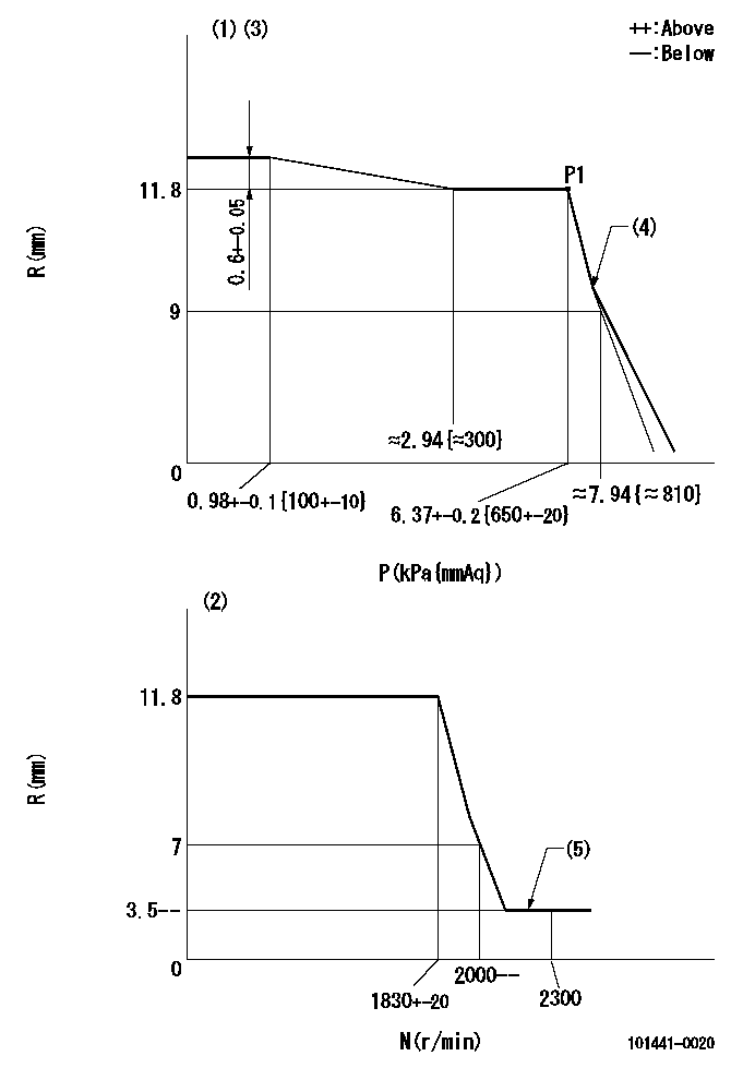
N:Pump speed
R:Rack position (mm)
P:Negative pressure
(1)Pneumatic governor
(2)Mechanical governor
(3)Acting negative pressure: P1
(4)Beginning of idle sub spring operation: L1
(5)Injection quantity Q = Q1 or less
----------
P1=6.37+-0.2kPa(650+-20mmAq) L1=9+0.3mm Q1=3mm3/st
----------
----------
P1=6.37+-0.2kPa(650+-20mmAq) L1=9+0.3mm Q1=3mm3/st
----------
Stop lever angle
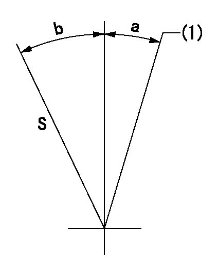
S:Stop the pump.
(1)Rack position = at least aa
----------
aa=17.5mm
----------
a=(14deg) b=(23deg)
----------
aa=17.5mm
----------
a=(14deg) b=(23deg)
Timing setting

(1)Pump vertical direction
(2)Position of key groove at No 1 cylinder's beginning of injection
(3)-
(4)-
----------
----------
a=(130deg)
----------
----------
a=(130deg)
Information:
Introduction
This Special Instruction contains the necessary procedure in order to install unit injectors for 3114, 3116, and 3126 MUI engines.Removal and Installation Procedure
Note: To avoid damage to the unit injector during removal of the unit injector from the cylinder head, refer to the Service Manual for the removal procedure of the unit injector.Use the latest process for servicing the unit injector sleeves in the cylinder head before you install replacement unit injectors. Refer to the Service Manual and other service news articles in order to find the latest service information, including new tools and procedures.Before a new unit injector or a remanufactured unit injector is installed into an engine, take adequate precautions in order to clean the internal fuel lines and the unit injector sleeve. Also, install a new Caterpillar high efficiency fuel filter.Lubricate the injector rack bar with clean diesel fuel or 1U-8265 Penetrating Oil .
Illustration 1 g02144296
Incorrect testing procedure for the tappet springDo not depress the tappet spring. Refer to Illustration 1. Do not force the injector rack bar in and out since this action may damage the internal parts of the unit injector. A tight rack on a unit injector that is not installed in the engine is not an indication of a faulty unit injector. Forcing the injector rack bar in and out may cause the unit injector to become damaged. Forcing the injector rack bar in and out may possibly void all the warranty.Do not test the unit injectors prior to engine installation. The unit injectors are tested 100% at the factory and Pop Testing may contaminate the unit injector.Before you install the unit injector, apply clean engine oil on the O-ring seals for ease of installation.Install the unit injector according to the procedure in the Service Manual by using 173-1530 Injector Seating Tool . Tighten the unit injector clamp retaining bolt to a torque of 12 3 N m (9 2 lb ft).Verify the following parameters and settings according to the procedures in the Service Manual: unit injector synchronization, fuel setting, fuel timing and valve lash. Adjust the parameters and settings in order to meet specifications only.
Have questions with 101441-0020?
Group cross 101441-0020 ZEXEL
Isuzu
101441-0020
9812007961
INJECTION-PUMP ASSEMBLY
C240
C240