Information injection-pump assembly
BOSCH
9 400 619 678
9400619678
ZEXEL
101433-9510
1014339510
Rating:
Service parts 101433-9510 INJECTION-PUMP ASSEMBLY:
1.
_
6.
COUPLING PLATE
7.
COUPLING PLATE
8.
_
9.
_
11.
Nozzle and Holder
1660090019
12.
Open Pre:MPa(Kqf/cm2)
9.8{100}
15.
NOZZLE SET
Include in #1:
101433-9510
as INJECTION-PUMP ASSEMBLY
Include in #2:
104242-1040
as _
Cross reference number
BOSCH
9 400 619 678
9400619678
ZEXEL
101433-9510
1014339510
Zexel num
Bosch num
Firm num
Name
Calibration Data:
Adjustment conditions
Test oil
1404 Test oil ISO4113 or {SAEJ967d}
1404 Test oil ISO4113 or {SAEJ967d}
Test oil temperature
degC
40
40
45
Nozzle and nozzle holder
105780-8140
Bosch type code
EF8511/9A
Nozzle
105780-0000
Bosch type code
DN12SD12T
Nozzle holder
105780-2080
Bosch type code
EF8511/9
Opening pressure
MPa
17.2
Opening pressure
kgf/cm2
175
Injection pipe
Outer diameter - inner diameter - length (mm) mm 6-2-600
Outer diameter - inner diameter - length (mm) mm 6-2-600
Tester oil delivery pressure
kPa
157
157
157
Tester oil delivery pressure
kgf/cm2
1.6
1.6
1.6
Direction of rotation (viewed from drive side)
Right R
Right R
Injection timing adjustment
Direction of rotation (viewed from drive side)
Right R
Right R
Injection order
1-3-4-2
Pre-stroke
mm
2.3
2.25
2.35
Beginning of injection position
Drive side NO.1
Drive side NO.1
Difference between angles 1
Cal 1-3 deg. 90 89.5 90.5
Cal 1-3 deg. 90 89.5 90.5
Difference between angles 2
Cal 1-4 deg. 180 179.5 180.5
Cal 1-4 deg. 180 179.5 180.5
Difference between angles 3
Cyl.1-2 deg. 270 269.5 270.5
Cyl.1-2 deg. 270 269.5 270.5
Injection quantity adjustment
Adjusting point
A
Rack position
14.1
Pump speed
r/min
1550
1550
1550
Average injection quantity
mm3/st.
35.7
34.7
36.7
Max. variation between cylinders
%
0
-2.5
2.5
Basic
*
Fixing the lever
*
Injection quantity adjustment_02
Adjusting point
B
Rack position
10.8+-0.
5
Pump speed
r/min
300
300
300
Average injection quantity
mm3/st.
7.5
6.5
8.5
Max. variation between cylinders
%
0
-15
15
Fixing the rack
*
Remarks
Adjust only variation between cylinders; adjust governor according to governor specifications.
Adjust only variation between cylinders; adjust governor according to governor specifications.
Timer adjustment
Pump speed
r/min
500
Advance angle
deg.
0.5
Timer adjustment_02
Pump speed
r/min
550
Advance angle
deg.
0.7
Timer adjustment_03
Pump speed
r/min
700
Advance angle
deg.
1
0.5
1.5
Timer adjustment_04
Pump speed
r/min
900
Advance angle
deg.
2
1.5
2.5
Timer adjustment_05
Pump speed
r/min
1100
Advance angle
deg.
3
2.5
3.5
Timer adjustment_06
Pump speed
r/min
1300
Advance angle
deg.
4
3.5
4.5
Timer adjustment_07
Pump speed
r/min
1500
Advance angle
deg.
5
4.5
5.5
Remarks
Finish
Finish
Test data Ex:
Governor adjustment
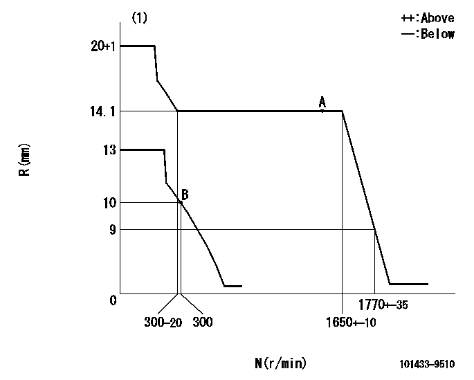
N:Pump speed
R:Rack position (mm)
(1)Target notch: K
----------
K=7
----------
----------
K=7
----------
Speed control lever angle
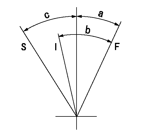
F:Full speed
I:Idle
S:Stop
----------
----------
a=(28deg)+-5deg b=(34deg)+-5deg c=32deg+-3deg
----------
----------
a=(28deg)+-5deg b=(34deg)+-5deg c=32deg+-3deg
Stop lever angle

N:Pump normal
S:Stop the pump.
----------
----------
a=10deg+-5deg b=53deg+-5deg
----------
----------
a=10deg+-5deg b=53deg+-5deg
0000001501 GOV FULL LOAD ADJUSTMENT
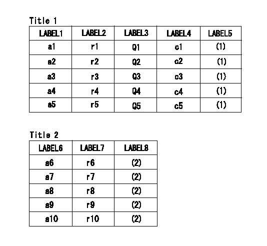
Title1:Full load stopper adjustment
Title2:Governor set speed
LABEL1:Distinguishing
LABEL2:Pump speed (r/min)
LABEL3:Ave. injection quantity (mm3/st)
LABEL4:Max. var. bet. cyl.
LABEL5:Remarks
LABEL6:Distinguishing
LABEL7:Governor set speed (r/min)
LABEL8:Remarks
(1)Adjustment conditions are the same as those for measuring injection quantity.
(2)-
----------
----------
a1=M a2=F a3=WD a4=WE a5=- r1=1550r/min r2=1550r/min r3=1550r/min r4=1550r/min r5=- Q1=35.7+-1mm3/st Q2=33.6+-1mm3/st Q3=35.7+-1mm3/st Q4=33.6+-1mm3/st Q5=- c1=+-2.5% c2=+-2.5% c3=+-2.5% c4=+-2.5% c5=- a6=- a7=- a8=- a9=- a10=- r6=- r7=- r8=- r9=- r10=-
----------
----------
a1=M a2=F a3=WD a4=WE a5=- r1=1550r/min r2=1550r/min r3=1550r/min r4=1550r/min r5=- Q1=35.7+-1mm3/st Q2=33.6+-1mm3/st Q3=35.7+-1mm3/st Q4=33.6+-1mm3/st Q5=- c1=+-2.5% c2=+-2.5% c3=+-2.5% c4=+-2.5% c5=- a6=- a7=- a8=- a9=- a10=- r6=- r7=- r8=- r9=- r10=-
Timing setting
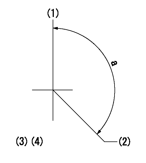
(1)Pump vertical direction
(2)Position of gear mark 'Y' at No 1 cylinder's beginning of injection
(3)-
(4)-
----------
----------
a=(130deg)
----------
----------
a=(130deg)
Information:
4N8735 Oil Pump (Two Section Gear)
Before operation, the pump must be lubricated with clean engine oil and the pump must turn freely by hand or damage to parts can be the result.
Section A:Rotation (viewed from the drive end) ... counterclockwiseTest on test stand, with SAE 10W oil at 49°C (120°F)Output ... 193 liter/min (51 U.S. gpm)With pump at ... 2550 rpm Section B:Rotation (viewed from the drive end) ... counterclockwiseTest on test stand, with SAE 10W oil at 49°C (120°F)Output ... 272 liter/min (72 U.S. gpm)At a pressure of ... 310 kPa (45 psi)With pump at ... 2550 rpmOutput ... 144 liter/min (38 U.S. gpm) At a pressure of ... 560 kPa (81 psi)With pump at ... 2550 rpm(1) Diameter of drive shaft (new) ... 20.320 0.005 mm (.8000 .0002 in) Bore in bearings for drive shaft (new) ... 20.361 0.008 mm (.8016 .0003 in)(2) Diameter of idler shaft (new) ... 20.320 0.005 mm (.8000 .0002 in) Bore in bearings for drive shaft (new) ... 20.361 0.008 mm (.8016 .0003 in)(3) Length of gears (new) ... 57.158 0.025 mm (2.2503 .0010 in) Depth of bores for gears (new) ... 57.285 0.020 mm (2.2553 .0008 in)(4) Diameter of drive shaft (new) ... 22.217 0.005 mm (.8747 .0002 in) Bore in bearings for drive shaft (new) ... 22.258 0.008 mm (.8763 .0003 in)(5) Diameter of idler shaft (new) ... 22.217 0.005 mm (.8747 .0002 in) Bore in bearings for drive shaft (new) ... 22.258 0.008 mm (.8763 .0003 in)(6) Length of gears (new) ... 79.375 0.025 mm (3.1250 .0010 in) Depth of bores for gears (new) ... 79.502 0.020 mm (3.1300 .0008 in)(7) Diameter of drive shaft (new) ... 22.217 0.005 mm (.8747 .0002 in) Bore in bearings for drive shaft (new) ... 22.258 0.008 mm (.8763 .0003 in)(8) Diameter of idler shaft (new) ... 22.217 0.005 mm (.8747 .0002 in) Bore in bearings for drive shaft (new) ... 22.258 0.008 mm (.8763 .0003 in) (9) 2S2760 Spring (oil pressure relief valve): Length under test force ... 117.9 mm (4.64 in)Test force ... 490 27 N (110 6 lb)Free length after test ... 152.9 mm (6.02 in)Outside diameter ... 27.00 mm (1.063 in)
Pump Body - Section A(10) Install bearings to depth ... 1.52 mm (.060 in)(11) Bearing junction.(12) Position of bearing junction from the centerline through
