Information injection-pump assembly
BOSCH
9 400 610 064
9400610064
ZEXEL
101433-9210
1014339210
NISSAN-DIESEL
16700L2500
16700l2500

Rating:
Service parts 101433-9210 INJECTION-PUMP ASSEMBLY:
1.
_
6.
COUPLING PLATE
7.
COUPLING PLATE
8.
_
9.
_
11.
Nozzle and Holder
16600-90019
12.
Open Pre:MPa(Kqf/cm2)
9.8{100}

15.
NOZZLE SET
Include in #1:
101433-9210
as INJECTION-PUMP ASSEMBLY
Include in #2:
105856-1741
as _
Cross reference number
BOSCH
9 400 610 064
9400610064
ZEXEL
101433-9210
1014339210
NISSAN-DIESEL
16700L2500
16700l2500
Zexel num
Bosch num
Firm num
Name
101433-9210
9 400 610 064
16700L2500 NISSAN-DIESEL
INJECTION-PUMP ASSEMBLY
SD22 * K 14BC PE4A,5A, PE
SD22 * K 14BC PE4A,5A, PE
Calibration Data:
Adjustment conditions
Test oil
1404 Test oil ISO4113 or {SAEJ967d}
1404 Test oil ISO4113 or {SAEJ967d}
Test oil temperature
degC
40
40
45
Nozzle and nozzle holder
105780-8140
Bosch type code
EF8511/9A
Nozzle
105780-0000
Bosch type code
DN12SD12T
Nozzle holder
105780-2080
Bosch type code
EF8511/9
Opening pressure
MPa
17.2
Opening pressure
kgf/cm2
175
Injection pipe
Outer diameter - inner diameter - length (mm) mm 6-2-600
Outer diameter - inner diameter - length (mm) mm 6-2-600
Tester oil delivery pressure
kPa
157
157
157
Tester oil delivery pressure
kgf/cm2
1.6
1.6
1.6
Direction of rotation (viewed from drive side)
Right R
Right R
Injection timing adjustment
Direction of rotation (viewed from drive side)
Right R
Right R
Injection order
1-3-4-2
Pre-stroke
mm
2.3
2.25
2.35
Beginning of injection position
Drive side NO.1
Drive side NO.1
Difference between angles 1
Cal 1-3 deg. 90 89.5 90.5
Cal 1-3 deg. 90 89.5 90.5
Difference between angles 2
Cal 1-4 deg. 180 179.5 180.5
Cal 1-4 deg. 180 179.5 180.5
Difference between angles 3
Cyl.1-2 deg. 270 269.5 270.5
Cyl.1-2 deg. 270 269.5 270.5
Injection quantity adjustment
Adjusting point
-
Rack position
14.9
Pump speed
r/min
800
800
800
Average injection quantity
mm3/st.
36.6
35.6
37.6
Max. variation between cylinders
%
0
-2.5
2.5
Basic
*
Fixing the rack
*
Injection quantity adjustment_02
Adjusting point
-
Rack position
13.9
Pump speed
r/min
1700
1700
1700
Average injection quantity
mm3/st.
36.6
35
38.2
Max. variation between cylinders
%
0
-4
4
Fixing the rack
*
Injection quantity adjustment_03
Adjusting point
-
Rack position
9
Pump speed
r/min
1700
1700
1700
Average injection quantity
mm3/st.
7
6.2
7.8
Max. variation between cylinders
%
0
-7.5
7.5
Fixing the rack
*
Injection quantity adjustment_04
Adjusting point
-
Rack position
10.8
Pump speed
r/min
300
300
300
Average injection quantity
mm3/st.
7.5
6.4
8.6
Max. variation between cylinders
%
0
-15
15
Fixing the rack
*
Timer adjustment
Pump speed
r/min
500
Advance angle
deg.
0.5
Timer adjustment_02
Pump speed
r/min
550
Advance angle
deg.
0.7
Timer adjustment_03
Pump speed
r/min
700
Advance angle
deg.
1
0.5
1.5
Timer adjustment_04
Pump speed
r/min
900
Advance angle
deg.
2
1.5
2.5
Timer adjustment_05
Pump speed
r/min
1100
Advance angle
deg.
3
2.5
3.5
Timer adjustment_06
Pump speed
r/min
1300
Advance angle
deg.
4
3.5
4.5
Timer adjustment_07
Pump speed
r/min
1500
Advance angle
deg.
5
4.5
5.5
Remarks
Finish
Finish
Test data Ex:
Governor adjustment
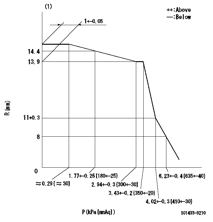
P:Negative pressure
R:Rack position (mm)
(1)Pneumatic governor
----------
----------
----------
----------
0000001101
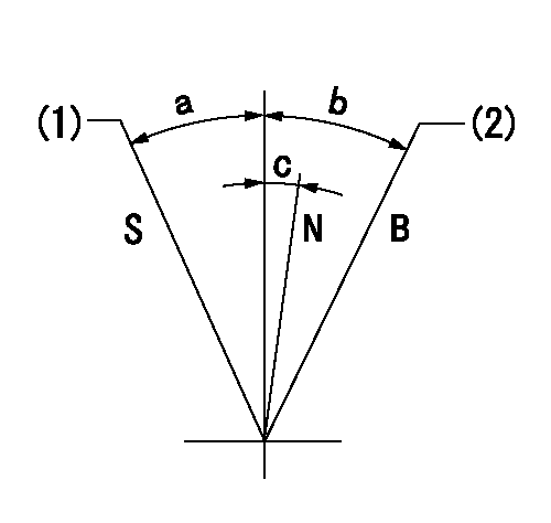
S:Stop
N:Normal
B:When boosted
(1)Rack position = approximately aa.
(2)Rack position corresponding to bb
----------
aa=3.5mm bb=21mm
----------
a=24.5deg b=12deg c=4deg+-5deg
----------
aa=3.5mm bb=21mm
----------
a=24.5deg b=12deg c=4deg+-5deg
Timing setting

(1)Pump vertical direction
(2)Position of gear mark 'Y' at No 1 cylinder's beginning of injection
(3)-
(4)-
----------
----------
a=(130deg)
----------
----------
a=(130deg)
Information:
3. Turn the engine to the top center (TC) compression stroke for the No. 1 piston.4. Remove bolts (1), cover assembly (2) and the gasket from the front housing. 5. Remove two bolts (3). Carefully remove thrust plate (4) and the camshaft assembly from the engine.6. Remove drive gear (5) from the camshaft with a press. Remove the woodruff key from the camshaft. The following steps are for the installation of the camshaft.7. Install the woodruff key in the camshaft. Heat drive gear (5) to a maximum temperature of 316°C (600°F). Do not use a torch to heat the drive gear. Install the drive gear on the camshaft, and allow it to cool.
Camshaft timing is very important. When the camshaft assembly is installed, be sure the No. 1 piston is at top center (TC) of the compression stroke. The timing marks on the camshaft drive gear, the idler gear and the crankshaft idler gear must be in alignment as shown in Illustration C21075P5. For more information regarding timing of the engine, see the topic "Front Gear Group" in the 3114 & 3116 Diesel Truck Engine Specifications module, Form No. SENR6436.
8. Apply clean engine oil on the lobes and journals of the camshaft. Carefully install the camshaft assembly in the cylinder block.9. Put thrust plate (4) in position, and install bolts (3) that hold it.10. Be sure the mating surfaces of the front housing and cover assembly (2) are thoroughly clean. Apply 8C8422 Sealant to the cover assembly sealing surface. Spread the sealant uniformly and around each bolt hole. The cover assembly must be installed on the front housing within ten minutes of sealant application.11. Put the gasket and cover assembly (2) in position on the front housing. Install bolts (1) that hold the cover assembly to the front housing.12. Install the vibration damper and the crankshaft pulley. See the topic "Remove & Install Vibration Damper, Crankshaft Pulley & Crankshaft Front Seal" in this module.13. Install the governor and fuel transfer pump. See the topic "Remove & Install Governor & Fuel Transfer Pump" in this module.End By:a. Install lifter assemblies
Have questions with 101433-9210?
Group cross 101433-9210 ZEXEL
Nissan-Diesel
101433-9210
9 400 610 064
16700L2500
INJECTION-PUMP ASSEMBLY
SD22
SD22