Information injection-pump assembly
ZEXEL
101433-9140
1014339140
NISSAN-DIESEL
16700V0603
16700v0603
Rating:
Service parts 101433-9140 INJECTION-PUMP ASSEMBLY:
1.
_

6.
COUPLING PLATE
7.
COUPLING PLATE
8.
_
9.
_
11.
Nozzle and Holder
16600-20053
12.
Open Pre:MPa(Kqf/cm2)
9.8{100}

15.
NOZZLE SET
Cross reference number
ZEXEL
101433-9140
1014339140
NISSAN-DIESEL
16700V0603
16700v0603
Zexel num
Bosch num
Firm num
Name
101433-9140
16700V0603 NISSAN-DIESEL
INJECTION-PUMP ASSEMBLY
SD20 * K
SD20 * K
Calibration Data:
Adjustment conditions
Test oil
1404 Test oil ISO4113 or {SAEJ967d}
1404 Test oil ISO4113 or {SAEJ967d}
Test oil temperature
degC
40
40
45
Nozzle and nozzle holder
105780-8140
Bosch type code
EF8511/9A
Nozzle
105780-0000
Bosch type code
DN12SD12T
Nozzle holder
105780-2080
Bosch type code
EF8511/9
Opening pressure
MPa
17.2
Opening pressure
kgf/cm2
175
Injection pipe
Outer diameter - inner diameter - length (mm) mm 6-2-600
Outer diameter - inner diameter - length (mm) mm 6-2-600
Tester oil delivery pressure
kPa
157
157
157
Tester oil delivery pressure
kgf/cm2
1.6
1.6
1.6
Direction of rotation (viewed from drive side)
Right R
Right R
Injection timing adjustment
Direction of rotation (viewed from drive side)
Right R
Right R
Injection order
1-3-4-2
Pre-stroke
mm
2.3
2.25
2.35
Rack position
Point B R=B
Point B R=B
Beginning of injection position
Drive side NO.1
Drive side NO.1
Difference between angles 1
Cal 1-3 deg. 90 89.5 90.5
Cal 1-3 deg. 90 89.5 90.5
Difference between angles 2
Cal 1-4 deg. 180 179.5 180.5
Cal 1-4 deg. 180 179.5 180.5
Difference between angles 3
Cyl.1-2 deg. 270 269.5 270.5
Cyl.1-2 deg. 270 269.5 270.5
Injection quantity adjustment
Adjusting point
A
Rack position
11.6
Pump speed
r/min
800
800
800
Average injection quantity
mm3/st.
34
33.1
34.9
Max. variation between cylinders
%
0
-2.5
2.5
Basic
*
Fixing the rack
*
Injection quantity adjustment_02
Adjusting point
B
Rack position
10.6
Pump speed
r/min
1700
1700
1700
Average injection quantity
mm3/st.
34.3
32.8
35.8
Max. variation between cylinders
%
0
-4
4
Fixing the rack
*
Injection quantity adjustment_03
Adjusting point
C
Rack position
6
Pump speed
r/min
1700
1700
1700
Average injection quantity
mm3/st.
8
7.2
8.8
Max. variation between cylinders
%
0
-7.5
7.5
Fixing the rack
*
Injection quantity adjustment_04
Adjusting point
D
Rack position
7.7
Pump speed
r/min
300
300
300
Average injection quantity
mm3/st.
7.5
6.4
8.6
Max. variation between cylinders
%
0
-15
15
Fixing the rack
*
Injection quantity adjustment_05
Adjusting point
-
Rack position
-
Pump speed
r/min
800
800
800
Average injection quantity
mm3/st.
34
33.5
34.5
Remarks
Smoke setting
Smoke setting
Timer adjustment
Pump speed
r/min
500
Advance angle
deg.
0.3
Timer adjustment_02
Pump speed
r/min
550
Advance angle
deg.
0.5
Timer adjustment_03
Pump speed
r/min
800
Advance angle
deg.
0.7
0.2
1.2
Timer adjustment_04
Pump speed
r/min
1000
Advance angle
deg.
1.4
0.9
1.9
Timer adjustment_05
Pump speed
r/min
1200
Advance angle
deg.
2.3
1.8
2.8
Timer adjustment_06
Pump speed
r/min
1400
Advance angle
deg.
3.3
2.8
3.8
Timer adjustment_07
Pump speed
r/min
1650
Advance angle
deg.
5
4.5
5.5
Remarks
Finish
Finish
Test data Ex:
Governor adjustment
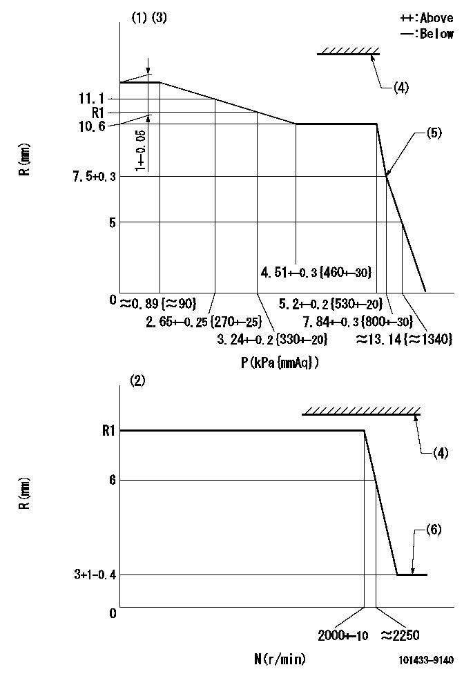
N:Pump speed
R:Rack position (mm)
P:Negative pressure
(1)Pneumatic governor
(2)Mechanical governor
(3)Acting negative pressure: P1
(4)RACK LIMIT: RAL
(5)Beginning of idle sub spring operation: L1
(6)Injection quantity Q = Q1 or less
----------
P1=3.24+-0.2kPa(330+-20mmAq) RAL=16mm L1=7.5+0.3mm Q1=3mm3/st
----------
----------
P1=3.24+-0.2kPa(330+-20mmAq) RAL=16mm L1=7.5+0.3mm Q1=3mm3/st
----------
Speed control lever angle
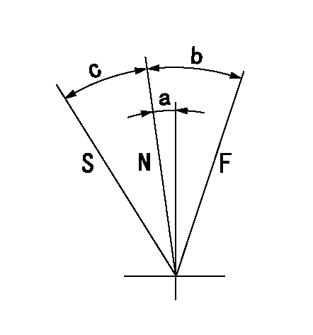
F:Full speed
N:Normal
S:Stop
----------
----------
a=4.5deg+-5deg b=13deg+-5deg c=19.5deg+-3deg
----------
----------
a=4.5deg+-5deg b=13deg+-5deg c=19.5deg+-3deg
Timing setting

(1)Pump vertical direction
(2)Position of gear mark 'Y' at No 1 cylinder's beginning of injection
(3)-
(4)-
----------
----------
a=(130deg)
----------
----------
a=(130deg)
Information:
Start Bya. remove flywheel
Do not damage the flange on the crankshaft when the crankshaft rear seal is removed. Use of any other tool, other than Tool (A), to remove the crankshaft rear seal, can result in damage to the crankshaft.
1. Carefully make three evenly spaced holes in the crankshaft rear seal with a hammer and sharp punch. Use Tool (A) to remove crankshaft rear seal (1). Do not damage the flange of the crankshaft during seal removal. The following steps are for the installation of the crankshaft rear seal.2. Be sure the flange of the crankshaft is thoroughly clean prior to seal installation. 3. Fasten the 1U7595 Locator Assembly [part of Tool (B)] to the rear of the crankshaft as shown.4. Leaving the seal shipping sleeve in position on the new crankshaft rear seal, position the new seal over the locator assembly. The 1U7597 Sleeve Ring [part of Tool (B)] is not used in this in the seal installation.5. Install the 1U7594 Installer [part of Tool (B)] on the locator assembly. Tighten the nut assembly of Tool (B) to push the crankshaft rear seal into position on the flange of the crankshaft. Remove Tool (B) and the shipping sleeve. The distance between the front face of the crankshaft rear seal and the rear face of the cylinder block must be 15.4 0.5 mm (.61 .02 in) after seal installation. See the topic "Crankshaft Seals" in the 3114 & 3116 Diesel Truck Engines Specifications module, Form No. SENR6436 for further details.End By:a. install flywheel
Have questions with 101433-9140?
Group cross 101433-9140 ZEXEL
Nissan-Diesel
101433-9140
16700V0603
INJECTION-PUMP ASSEMBLY
SD20
SD20