Information injection-pump assembly
ZEXEL
101433-9120
1014339120
NISSAN-DIESEL
16700Y7506
16700y7506
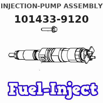
Rating:
Service parts 101433-9120 INJECTION-PUMP ASSEMBLY:
1.
_
6.
COUPLING PLATE
7.
COUPLING PLATE
8.
_
9.
_
11.
Nozzle and Holder
16600-20053
12.
Open Pre:MPa(Kqf/cm2)
9.8{100}
15.
NOZZLE SET
Cross reference number
ZEXEL
101433-9120
1014339120
NISSAN-DIESEL
16700Y7506
16700y7506
Zexel num
Bosch num
Firm num
Name
101433-9120
16700Y7506 NISSAN-DIESEL
INJECTION-PUMP ASSEMBLY
SD20 * K
SD20 * K
Calibration Data:
Adjustment conditions
Test oil
1404 Test oil ISO4113 or {SAEJ967d}
1404 Test oil ISO4113 or {SAEJ967d}
Test oil temperature
degC
40
40
45
Nozzle and nozzle holder
105780-8140
Bosch type code
EF8511/9A
Nozzle
105780-0000
Bosch type code
DN12SD12T
Nozzle holder
105780-2080
Bosch type code
EF8511/9
Opening pressure
MPa
17.2
Opening pressure
kgf/cm2
175
Injection pipe
Outer diameter - inner diameter - length (mm) mm 6-2-600
Outer diameter - inner diameter - length (mm) mm 6-2-600
Tester oil delivery pressure
kPa
157
157
157
Tester oil delivery pressure
kgf/cm2
1.6
1.6
1.6
Direction of rotation (viewed from drive side)
Right R
Right R
Injection timing adjustment
Direction of rotation (viewed from drive side)
Right R
Right R
Injection order
1-3-4-2
Pre-stroke
mm
2.3
2.25
2.35
Rack position
Point B R=B
Point B R=B
Beginning of injection position
Drive side NO.1
Drive side NO.1
Difference between angles 1
Cal 1-3 deg. 90 89.5 90.5
Cal 1-3 deg. 90 89.5 90.5
Difference between angles 2
Cal 1-4 deg. 180 179.5 180.5
Cal 1-4 deg. 180 179.5 180.5
Difference between angles 3
Cyl.1-2 deg. 270 269.5 270.5
Cyl.1-2 deg. 270 269.5 270.5
Injection quantity adjustment
Adjusting point
A
Rack position
11.6
Pump speed
r/min
800
800
800
Average injection quantity
mm3/st.
34
33.1
34.9
Max. variation between cylinders
%
0
-2.5
2.5
Basic
*
Fixing the rack
*
Injection quantity adjustment_02
Adjusting point
B
Rack position
10.6
Pump speed
r/min
1700
1700
1700
Average injection quantity
mm3/st.
34.3
32.8
35.8
Max. variation between cylinders
%
0
-4
4
Fixing the rack
*
Injection quantity adjustment_03
Adjusting point
C
Rack position
6
Pump speed
r/min
1700
1700
1700
Average injection quantity
mm3/st.
8
7.2
8.8
Max. variation between cylinders
%
0
-7.5
7.5
Fixing the rack
*
Injection quantity adjustment_04
Adjusting point
D
Rack position
7.7
Pump speed
r/min
300
300
300
Average injection quantity
mm3/st.
7.5
6.4
8.6
Max. variation between cylinders
%
0
-15
15
Fixing the rack
*
Injection quantity adjustment_05
Adjusting point
-
Rack position
-
Pump speed
r/min
800
800
800
Average injection quantity
mm3/st.
34
33.5
34.5
Remarks
Smoke setting
Smoke setting
Timer adjustment
Pump speed
r/min
500
Advance angle
deg.
0.3
Timer adjustment_02
Pump speed
r/min
550
Advance angle
deg.
0.5
Timer adjustment_03
Pump speed
r/min
800
Advance angle
deg.
0.7
0.2
1.2
Timer adjustment_04
Pump speed
r/min
1000
Advance angle
deg.
1.4
0.9
1.9
Timer adjustment_05
Pump speed
r/min
1200
Advance angle
deg.
2.3
1.8
2.8
Timer adjustment_06
Pump speed
r/min
1400
Advance angle
deg.
3.3
2.8
3.8
Timer adjustment_07
Pump speed
r/min
1650
Advance angle
deg.
5
4.5
5.5
Remarks
Finish
Finish
Test data Ex:
Governor adjustment
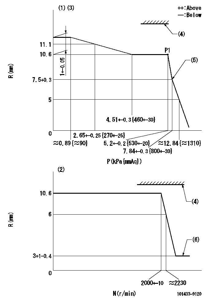
N:Pump speed
R:Rack position (mm)
P:Negative pressure
(1)Pneumatic governor
(2)Mechanical governor
(3)Acting negative pressure: P1
(4)RACK LIMIT: RAL
(5)Beginning of idle sub spring operation: L1
(6)Injection quantity Q = Q1 or less
----------
RAL=16mm L1=7.5+0.3mm Q1=3mm3/st
----------
----------
RAL=16mm L1=7.5+0.3mm Q1=3mm3/st
----------
Speed control lever angle
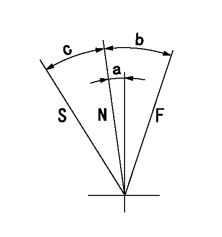
F:Full speed
N:Normal
S:Stop
----------
----------
a=4.5deg+-5deg b=13deg+-5deg c=19.5deg+-3deg
----------
----------
a=4.5deg+-5deg b=13deg+-5deg c=19.5deg+-3deg
Timing setting
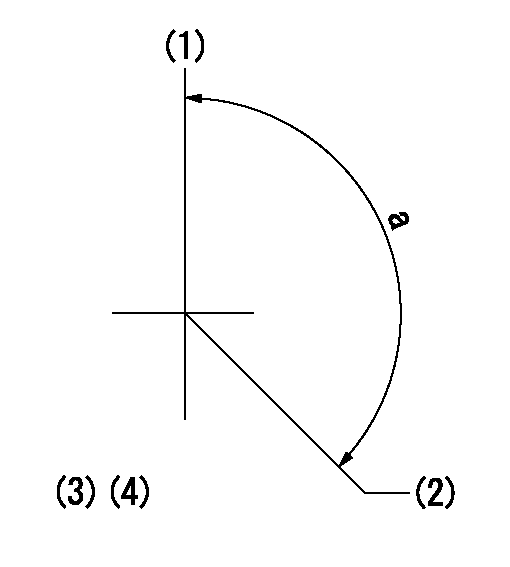
(1)Pump vertical direction
(2)Position of gear mark 'Y' at No 1 cylinder's beginning of injection
(3)-
(4)-
----------
----------
a=(130deg)
----------
----------
a=(130deg)
Information:
To prevent possible personal injury, do not disconnect any air lines from the air compressor until the air pressure in the system has been released.
1. Release the pressure in the air system. 2. Disconnect tube assembly (3) from the air compressor.3. Disconnect tube assembly (4) from the air compressor.4. Disconnect the two hose assemblies from locations (6) on the power steering pump.5. Disconnect the tube assembly at air inlet port (8).6. Disconnect the tube assembly at air outlet port (9).7. Disconnect the clip and hose assembly (7) at the air compressor.8. Remove two bolts (2) and the washers that hold the air compressor to the cylinder block.9. Fasten a lifting strap and a hoist to air compressor (1).10. Remove two bolts (5) and the washers that hold the air compressor to the front housing. Remove the air compressor and gasket from the front housing. The weight of the air compressor is 26 kg (57 lb).11. Remove the nut and washer that hold the drive gear to the air compressor. Remove the drive gear. The following steps are for the installation of the air compressor.12. Check the condition of the gasket used between the air compressor and front housing. If the gasket is damaged, use a new part for replacement.13. Put the drive gear in position on the air compressor, and install the washer and nut that hold it. Tighten the nut to a torque of 160 15 N m (120 11 lb ft).14. Put the gasket in position on the air compressor. Fasten a lifting strap and a hoist to air compressor (1). Put the compressor in position in the front housing. Install two bolts (5) and the washers that hold the compressor to the front housing.15. Install two bolts (2) and the washers that hold the air compressor to the cylinder block. First, tighten the bolts finger tight; then tighten the bolts to a torque of 55 10 N m (41 7 lb ft).16. Connect hose assembly (7) to the air compressor. Connect the clip that holds the hose assembly to the air compressor. Tighten the bolt that holds the clip to a torque of 40 8 N m (30 6 lb ft).17. Connect the tube assembly to air outlet port (9).18. Connect the tube assembly to air inlet port (8).19. Connect the two hose assemblies at locations (6) on the power steering pump.20. Connect tube assemblies (3) and (4) to the air compressor.
Have questions with 101433-9120?
Group cross 101433-9120 ZEXEL
Nissan-Diesel
101433-9120
16700Y7506
INJECTION-PUMP ASSEMBLY
SD20
SD20
