Information injection-pump assembly
ZEXEL
101433-9090
1014339090
NISSAN-DIESEL
16700Y8409
16700y8409

Rating:
Service parts 101433-9090 INJECTION-PUMP ASSEMBLY:
1.
_

6.
COUPLING PLATE
7.
COUPLING PLATE
8.
_
9.
_
11.
Nozzle and Holder
16600-20053
12.
Open Pre:MPa(Kqf/cm2)
9.8{100}

15.
NOZZLE SET
Cross reference number
ZEXEL
101433-9090
1014339090
NISSAN-DIESEL
16700Y8409
16700y8409
Zexel num
Bosch num
Firm num
Name
101433-9090
16700Y8409 NISSAN-DIESEL
INJECTION-PUMP ASSEMBLY
SD22 *
SD22 *
Calibration Data:
Adjustment conditions
Test oil
1404 Test oil ISO4113 or {SAEJ967d}
1404 Test oil ISO4113 or {SAEJ967d}
Test oil temperature
degC
40
40
45
Nozzle and nozzle holder
105780-8140
Bosch type code
EF8511/9A
Nozzle
105780-0000
Bosch type code
DN12SD12T
Nozzle holder
105780-2080
Bosch type code
EF8511/9
Opening pressure
MPa
17.2
Opening pressure
kgf/cm2
175
Injection pipe
Outer diameter - inner diameter - length (mm) mm 6-2-600
Outer diameter - inner diameter - length (mm) mm 6-2-600
Tester oil delivery pressure
kPa
157
157
157
Tester oil delivery pressure
kgf/cm2
1.6
1.6
1.6
Direction of rotation (viewed from drive side)
Right R
Right R
Injection timing adjustment
Direction of rotation (viewed from drive side)
Right R
Right R
Injection order
1-3-4-2
Pre-stroke
mm
2.3
2.25
2.35
Rack position
Point B R=B
Point B R=B
Beginning of injection position
Drive side NO.1
Drive side NO.1
Difference between angles 1
Cal 1-3 deg. 90 89.5 90.5
Cal 1-3 deg. 90 89.5 90.5
Difference between angles 2
Cal 1-4 deg. 180 179.5 180.5
Cal 1-4 deg. 180 179.5 180.5
Difference between angles 3
Cyl.1-2 deg. 270 269.5 270.5
Cyl.1-2 deg. 270 269.5 270.5
Injection quantity adjustment
Adjusting point
A
Rack position
12
Pump speed
r/min
800
800
800
Average injection quantity
mm3/st.
37
36
38
Max. variation between cylinders
%
0
-2.5
2.5
Basic
*
Fixing the rack
*
Injection quantity adjustment_02
Adjusting point
B
Rack position
11
Pump speed
r/min
1700
1700
1700
Average injection quantity
mm3/st.
37
35.4
38.6
Max. variation between cylinders
%
0
-4
4
Fixing the rack
*
Injection quantity adjustment_03
Adjusting point
C
Rack position
6
Pump speed
r/min
1700
1700
1700
Average injection quantity
mm3/st.
8
7.2
8.8
Max. variation between cylinders
%
0
-7.5
7.5
Fixing the rack
*
Injection quantity adjustment_04
Adjusting point
D
Rack position
7.7
Pump speed
r/min
300
300
300
Average injection quantity
mm3/st.
7.5
6.4
8.6
Max. variation between cylinders
%
0
-15
15
Fixing the rack
*
Injection quantity adjustment_05
Adjusting point
-
Rack position
-
Pump speed
r/min
800
800
800
Average injection quantity
mm3/st.
37
36.5
37.5
Remarks
Set full load.
Set full load.
Timer adjustment
Pump speed
r/min
500
Advance angle
deg.
0.5
Timer adjustment_02
Pump speed
r/min
550
Advance angle
deg.
0.7
Timer adjustment_03
Pump speed
r/min
700
Advance angle
deg.
1
0.5
1.5
Timer adjustment_04
Pump speed
r/min
900
Advance angle
deg.
2
1.5
2.5
Timer adjustment_05
Pump speed
r/min
1100
Advance angle
deg.
3
2.5
3.5
Timer adjustment_06
Pump speed
r/min
1300
Advance angle
deg.
4
3.5
4.5
Timer adjustment_07
Pump speed
r/min
1500
Advance angle
deg.
5
4.5
5.5
Remarks
Finish
Finish
Test data Ex:
Governor adjustment
N:Pump speed
R:Rack position (mm)
P:Negative pressure
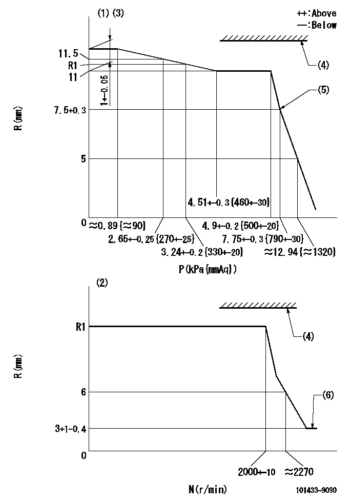
(1)Pneumatic governor
(2)Mechanical governor
(3)Acting negative pressure: P1
(4)RACK LIMIT: RAL
(5)Beginning of idle sub spring operation: L1
(6)Injection quantity Q = Q1 or less
----------
P1=3.24+-0.2kPa(330+-20mmAq) RAL=16mm L1=7.5+0.3mm Q1=3mm3/st
----------
----------
P1=3.24+-0.2kPa(330+-20mmAq) RAL=16mm L1=7.5+0.3mm Q1=3mm3/st
----------
Speed control lever angle
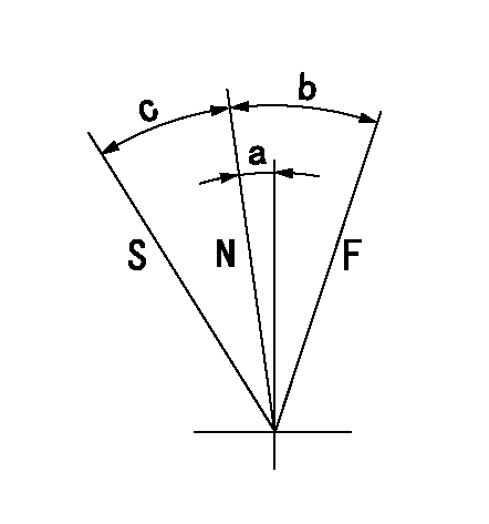
F:Full speed
N:Normal
S:Stop
----------
----------
a=3.5deg+-5deg b=12deg+-5deg c=20.5deg+-3deg
----------
----------
a=3.5deg+-5deg b=12deg+-5deg c=20.5deg+-3deg
Timing setting

(1)Pump vertical direction
(2)Position of gear mark 'Y' at No 1 cylinder's beginning of injection
(3)-
(4)-
----------
----------
a=(130deg)
----------
----------
a=(130deg)
Information:
At operating temperature, the engine coolant is hot and under pressure. Steam can cause personal injury. Check the coolant level only after the engine has been stopped and the fill cap is cool enough to touch with your bare hand. Remove the fill cap slowly to relieve pressure in the cooling system. Cooling system conditioner contains alkali. Avoid contact with skin and eyes to prevent personal injury.
1. Drain the coolant from the cooling system into a suitable container for storage or disposal.2. Remove the hose from the water temperature regulator housing. 3. Remove two bolts (1).4. Remove water temperature regulator housing (2) and the gasket from the cylinder head assembly. 5. Remove water temperature regulator (3) from the cylinder head assembly. The following steps are for the installation of the water temperature regulator.
If the water temperature regulator is installed wrong, it will cause the engine to overheat.
6. Put water temperature regulator (3) in position in the cylinder head assembly.7. Install a new gasket and water temperature regulator housing (2).8. Connect the hose to the water temperature regulator housing.9. Fill the cooling system with coolant to the correct level. See the topic "Cooling System" in the 3114 & 3116 ATAAC Diesel Truck Engine Operation & Maintenance Manual, Form No. SEBU6723.
Have questions with 101433-9090?
Group cross 101433-9090 ZEXEL
Nissan-Diesel
101433-9090
16700Y8409
INJECTION-PUMP ASSEMBLY
SD22
SD22