Information injection-pump assembly
ZEXEL
101432-0290
1014320290
ISUZU
5156014380
5156014380
Rating:
Cross reference number
ZEXEL
101432-0290
1014320290
ISUZU
5156014380
5156014380
Zexel num
Bosch num
Firm num
Name
Calibration Data:
Adjustment conditions
Test oil
1404 Test oil ISO4113 or {SAEJ967d}
1404 Test oil ISO4113 or {SAEJ967d}
Test oil temperature
degC
40
40
45
Nozzle and nozzle holder
105780-8140
Bosch type code
EF8511/9A
Nozzle
105780-0000
Bosch type code
DN12SD12T
Nozzle holder
105780-2080
Bosch type code
EF8511/9
Opening pressure
MPa
17.2
Opening pressure
kgf/cm2
175
Injection pipe
Outer diameter - inner diameter - length (mm) mm 6-2-600
Outer diameter - inner diameter - length (mm) mm 6-2-600
Tester oil delivery pressure
kPa
157
157
157
Tester oil delivery pressure
kgf/cm2
1.6
1.6
1.6
Direction of rotation (viewed from drive side)
Left L
Left L
Injection timing adjustment
Direction of rotation (viewed from drive side)
Left L
Left L
Injection order
1-3-4-2
Pre-stroke
mm
2.25
2.2
2.3
Beginning of injection position
Drive side NO.1
Drive side NO.1
Difference between angles 1
Cal 1-3 deg. 90 89.5 90.5
Cal 1-3 deg. 90 89.5 90.5
Difference between angles 2
Cal 1-4 deg. 180 179.5 180.5
Cal 1-4 deg. 180 179.5 180.5
Difference between angles 3
Cyl.1-2 deg. 270 269.5 270.5
Cyl.1-2 deg. 270 269.5 270.5
Injection quantity adjustment
Adjusting point
-
Rack position
12.5
Pump speed
r/min
750
750
750
Average injection quantity
mm3/st.
36.5
34.9
38.1
Max. variation between cylinders
%
0
-4
4
Fixing the rack
*
Injection quantity adjustment_02
Adjusting point
-
Rack position
11.7
Pump speed
r/min
1100
1100
1100
Average injection quantity
mm3/st.
34.4
33.4
35.4
Max. variation between cylinders
%
0
-2.5
2.5
Basic
*
Fixing the rack
*
Injection quantity adjustment_03
Adjusting point
-
Rack position
7.9+-0.5
Pump speed
r/min
350
350
350
Average injection quantity
mm3/st.
7.2
6.1
8.3
Max. variation between cylinders
%
0
-4
4
Fixing the rack
*
Remarks
Adjust only variation between cylinders; adjust governor according to governor specifications.
Adjust only variation between cylinders; adjust governor according to governor specifications.
Test data Ex:
Governor adjustment
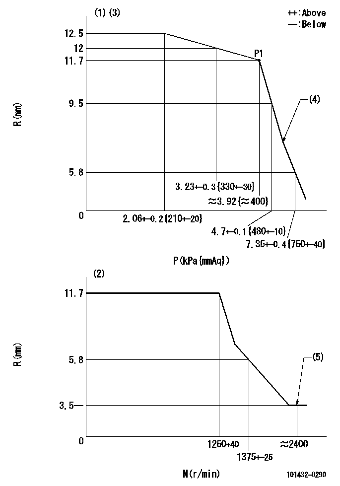
N:Pump speed
R:Rack position (mm)
P:Negative pressure
(1)Pneumatic governor
(2)Mechanical governor
(3)Acting negative pressure: P1
(4)Beginning of idle sub spring operation: L1
(5)Injection quantity Q = Q1 or less
----------
L1=6.9+-0.3mm Q1=3mm3/st
----------
----------
L1=6.9+-0.3mm Q1=3mm3/st
----------
Speed control lever angle
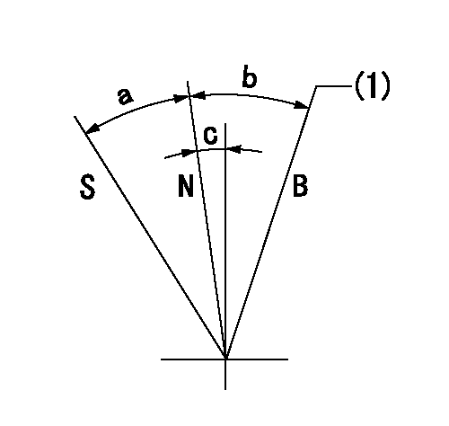
S:Stop
B:When boosted
N:Normal
(1)Rack position = aa
----------
aa=18mm
----------
a=23.5deg+-3deg b=15deg+-5deg c=2deg+-5deg
----------
aa=18mm
----------
a=23.5deg+-3deg b=15deg+-5deg c=2deg+-5deg
Timing setting

(1)Pump vertical direction
(2)Gear mark Z for the No. 4 cylinder's beginning of injection
(3)B.T.D.C.: aa
(4)-
----------
aa=18deg
----------
a=(60deg)
----------
aa=18deg
----------
a=(60deg)
Information:
(1) Bore in rocker arm for shaft ... 24.803 0.013 mm (.9765 .0005 in) Diameter of rocker arm shaft ... 24.752 0.013 mm (.9745 .0005 in)(2) Put 5P3931 Anti-Seize Compound on all the threads of bolts that hold rocker arm shafts and tighten the bolts in the step sequence that follows:1. Tighten bolts from 1 through 6 in number sequence to ... 270 27 N m (200 20 lb ft)2. Tighten bolts from 1 through 6 in number sequence to ... 450 20 N m (330 15 lb ft)3. Tighten bolts from 1 through 6 in number sequence again to ... 450 20 N m (330 15 lb ft) (3) Torque for locknut for valve adjustment screw ... 30 4 N m (22 3 lb ft)(4) Torque for locknut for bridge adjustment screw ... 30 4 N m (22 3 lb ft)(5) Valve lash: Intake valves ... 0.38 mm (.015 in)Exhaust valves ... 0.76 mm (.030 in)(6) Height to top of dowel ... 53.3 0.5 mm (2.10 .02 in)(7) Diameter of dowel ... 11.008 0.003 mm (.4334 .0001 in) Bore in bridge for dowel ... 11.13 0.05 mm (.438 .002 in)Bore in head for dowel ... 10.968 0.020 mm (.4318 .0008 in)(8) Diameter of valve lifter ... 27.896 0.013 mm (1.0983 .0005 in) Bore in block for valve lifter ... 27.953 0.019 mm (1.1005 .0008 in) See Guideline For Reusable Parts; Salvage Of Lifter Bores In 3400 Family Engines, Form No. SEBF8069 for the procedure, tooling and specifications needed to install 4W4588 Sleeves for salvage of the lifter bores in the cylinder block.(9) Guide springs must not be used again. Always install new guide springs. (10) 2N7229 Spring: Length under test force ... 74.2 mm (2.92 in)Test force ... 45 to 53 N (10 to 12 lb)Free length after test ... 114.3 mm (4.50 in)Outside diameter ... 29.7 mm (1.17 in)(11) Dowel length above top surface of rocker shaft support to be ... 12.7 1.0 mm (.50 .04 in)(12) Clearance for rocker arms (both ends) ... 0.30 to 1.40 mm (.012 to .055 in)(13) Use 2N7228 Washer as needed to get clearance (12). There must be a minimum of one 2N7228 Washer at each end of the rocker arm shaft. The bridge should be checked and/or adjusted each time the valves are adjusted. To check for wear use a dial indicator to measure the amount of wear on the bridge seat. Make sure the contact point on the dial indicator is small enough in diameter to get an accurate measurement. (A) Minimum dimension after reconditioning ... 16.51 mm (.650 in)(B) Allowable wear before reconditioning ... 0.13 mm (.005 in).Inspect the bridge seats for wear. Use the bridge again if the wear is 0.13 mm (.005 in) or less. When the wear seat is worn more than the allowable limit, the