Information injection-pump assembly
BOSCH
9 400 610 030
9400610030
ZEXEL
101431-9850
1014319850
NISSAN-DIESEL
16700Y8401
16700y8401

Rating:
Service parts 101431-9850 INJECTION-PUMP ASSEMBLY:
1.
_
6.
COUPLING PLATE
7.
COUPLING PLATE
8.
_
9.
_
11.
Nozzle and Holder
16600-90019
12.
Open Pre:MPa(Kqf/cm2)
9.8{100}
15.
NOZZLE SET
Cross reference number
BOSCH
9 400 610 030
9400610030
ZEXEL
101431-9850
1014319850
NISSAN-DIESEL
16700Y8401
16700y8401
Zexel num
Bosch num
Firm num
Name
101431-9850
9 400 610 030
16700Y8401 NISSAN-DIESEL
INJECTION-PUMP ASSEMBLY
SD22 * K
SD22 * K
Calibration Data:
Adjustment conditions
Test oil
1404 Test oil ISO4113 or {SAEJ967d}
1404 Test oil ISO4113 or {SAEJ967d}
Test oil temperature
degC
40
40
45
Nozzle and nozzle holder
105780-8140
Bosch type code
EF8511/9A
Nozzle
105780-0000
Bosch type code
DN12SD12T
Nozzle holder
105780-2080
Bosch type code
EF8511/9
Opening pressure
MPa
17.2
Opening pressure
kgf/cm2
175
Injection pipe
Outer diameter - inner diameter - length (mm) mm 6-2-600
Outer diameter - inner diameter - length (mm) mm 6-2-600
Tester oil delivery pressure
kPa
157
157
157
Tester oil delivery pressure
kgf/cm2
1.6
1.6
1.6
Direction of rotation (viewed from drive side)
Right R
Right R
Injection timing adjustment
Direction of rotation (viewed from drive side)
Right R
Right R
Injection order
1-3-4-2
Pre-stroke
mm
2.3
2.25
2.35
Beginning of injection position
Drive side NO.1
Drive side NO.1
Difference between angles 1
Cal 1-3 deg. 90 89.5 90.5
Cal 1-3 deg. 90 89.5 90.5
Difference between angles 2
Cal 1-4 deg. 180 179.5 180.5
Cal 1-4 deg. 180 179.5 180.5
Difference between angles 3
Cyl.1-2 deg. 270 269.5 270.5
Cyl.1-2 deg. 270 269.5 270.5
Injection quantity adjustment
Adjusting point
-
Rack position
12
Pump speed
r/min
800
800
800
Average injection quantity
mm3/st.
37.3
36.3
38.3
Max. variation between cylinders
%
0
-2.5
2.5
Basic
*
Fixing the rack
*
Injection quantity adjustment_02
Adjusting point
-
Rack position
11
Pump speed
r/min
1700
1700
1700
Average injection quantity
mm3/st.
37.3
35.7
38.9
Max. variation between cylinders
%
0
-4
4
Fixing the rack
*
Injection quantity adjustment_03
Adjusting point
-
Rack position
6
Pump speed
r/min
1700
1700
1700
Average injection quantity
mm3/st.
7
6.2
7.8
Max. variation between cylinders
%
0
-7.5
7.5
Fixing the rack
*
Injection quantity adjustment_04
Adjusting point
-
Rack position
7.7
Pump speed
r/min
300
300
300
Average injection quantity
mm3/st.
7.5
6.4
8.6
Max. variation between cylinders
%
0
-15
15
Fixing the rack
*
Injection quantity adjustment_05
Adjusting point
-
Rack position
-
Pump speed
r/min
800
800
800
Average injection quantity
mm3/st.
37.3
36.8
37.8
Remarks
Set full load.
Set full load.
Timer adjustment
Pump speed
r/min
500
Advance angle
deg.
0.5
Timer adjustment_02
Pump speed
r/min
550
Advance angle
deg.
0.7
Timer adjustment_03
Pump speed
r/min
700
Advance angle
deg.
1
0.5
1.5
Timer adjustment_04
Pump speed
r/min
900
Advance angle
deg.
2
1.5
2.5
Timer adjustment_05
Pump speed
r/min
1100
Advance angle
deg.
3
2.5
3.5
Timer adjustment_06
Pump speed
r/min
1300
Advance angle
deg.
4
3.5
4.5
Timer adjustment_07
Pump speed
r/min
1500
Advance angle
deg.
5
4.5
5.5
Remarks
Finish
Finish
Test data Ex:
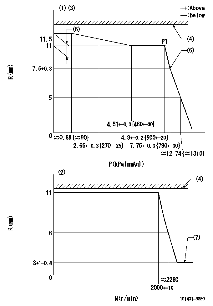
Governor adjustment

N:Pump speed
R:Rack position (mm)
P:Negative pressure
(1)Pneumatic governor
(2)Mechanical governor
(3)Acting negative pressure: P1
(4)RACK LIMIT: RAL
(5)Torque control stroke: L1
(6)Beginning of idle sub spring operation: L2
(7)Injection quantity Q = Q1 or less
----------
RAL=17mm L1=1+-0.05mm L2=7.5+0.3mm Q1=3mm3/st
----------
----------
RAL=17mm L1=1+-0.05mm L2=7.5+0.3mm Q1=3mm3/st
----------
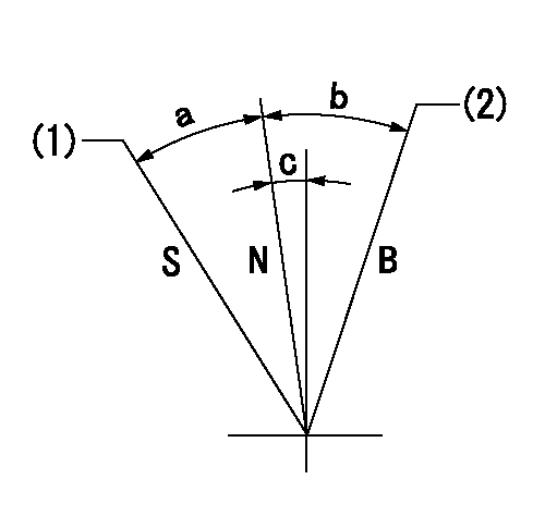
Speed control lever angle

S:Stop
B:When boosted
N:Normal
(1)Rack position = aa
(2)Rack position bb
----------
aa=(0.5)mm bb=17mm
----------
a=20.5deg+-3deg b=12deg+-5deg c=3.5deg+-5deg
----------
aa=(0.5)mm bb=17mm
----------
a=20.5deg+-3deg b=12deg+-5deg c=3.5deg+-5deg
Information:
Fuel Injection Pump
(1) Plug (timing pin hole)2. Remove plug (1) from the fuel injection pump housing.
Timing Pin Installed
(2) 6V4186 Timing Pin3. Install 6V4186 Timing Pin (2) in the fuel injection pump housing as shown. Slowly rotate the crankshaft counterclockwise (as seen from the flywheel end of the engine) until timing pin (2) goes into the slot in the fuel pump camshaft.
Timing Position Sensor Cover
(3) Cover (4) Housing (5) Timing Solenoid (BTM)4. Remove the timing position sensor cover (3) from housing (4).5. Rotate the crankshaft clockwise 15 degrees as seen from the flywheel end of the engine. Observe the motion of the timing advance power piston through housing (4).6. Rotate the crankshaft in the counterclockwise direction as seen from the rear of the engine until the timing advance power piston moves to its fully retracted position and light pressure is applied to the timing pin (2). Do not apply excessive force to rotate the engine with the timing pin installed. Excessive force will shear off the timing pin and/or cause fuel pump damage. Apply only enough force to retract the timing actuator power piston.
Install Timing Bolt
(6) 9S9082 Engine Turning Tool (7) Timing Bolt7. Put timing bolt in the timing hole in the flywheel housing. If the bolt can be installed in the timing hole in the flywheel, the static injection timing of the fuel injection pump is correct.8. If the timing bolt does not go into the timing hole in the flywheel, the timing is not correct. Perform the following steps to adjust the fuel injection pump static timing:
Automatic Timing Advance Unit
(Governor and Fuel Pump Drive Group) (8) BoltsA. Remove timing solenoid (BTM) (5).B. Remove timing advance housing (4).C. Loosen the four bolts (8) on the timing advance. With the timing pin installed in the fuel pump and the timing bolt removed, turn the engine crank shaft clockwise as viewed from the rear of the engine a minimum of 30 degrees. Make sure that the power piston of the timing advance does not move from its fully retracted position.D. Lightly tighten two of the four timing advance bolts to 2.3 N m (21 lb ft). Finger tight only so as not to bend the timing pin.E. Rotate the crankshaft counterclockwise as viewed from the rear of the engine (direction of rotation) slowly until the timing bolt can be installed in the flywheel. The number one piston is now at top dead center.F. Tighten the four timing advance bolts (8) to a torque of 10 N m (7 lb ft). Remove the timing pin from the fuel injection pump.G. Tighten the four timing advance bolts to a torque of 55 7 N m (41 5 lb ft). Remove the timing bolt from the flywheel.H. Turn the crankshaft two complete revolutions counterclockwise as viewed from the rear of the engine to make sure that the timing advance piston is in the fully retracted position. Repeat step 6 and 7 to check the timing again to see if the timing
Have questions with 101431-9850?
Group cross 101431-9850 ZEXEL
Nissan-Diesel
101431-9850
9 400 610 030
16700Y8401
INJECTION-PUMP ASSEMBLY
SD22
SD22
