Information injection-pump assembly
BOSCH
9 400 614 079
9400614079
ZEXEL
101421-4850
1014214850
ISUZU
5156006971
5156006971

Rating:
Include in #1:
106671-4521
as _
Cross reference number
BOSCH
9 400 614 079
9400614079
ZEXEL
101421-4850
1014214850
ISUZU
5156006971
5156006971
Zexel num
Bosch num
Firm num
Name
101421-4850
9 400 614 079
5156006971 ISUZU
INJECTION-PUMP ASSEMBLY
C190KR * K 14BC INJECTION PUMP ASSY PE4A,5A, PE
C190KR * K 14BC INJECTION PUMP ASSY PE4A,5A, PE
Calibration Data:
Adjustment conditions
Test oil
1404 Test oil ISO4113 or {SAEJ967d}
1404 Test oil ISO4113 or {SAEJ967d}
Test oil temperature
degC
40
40
45
Nozzle and nozzle holder
105780-8140
Bosch type code
EF8511/9A
Nozzle
105780-0000
Bosch type code
DN12SD12T
Nozzle holder
105780-2080
Bosch type code
EF8511/9
Opening pressure
MPa
17.2
Opening pressure
kgf/cm2
175
Injection pipe
Outer diameter - inner diameter - length (mm) mm 6-2-600
Outer diameter - inner diameter - length (mm) mm 6-2-600
Tester oil delivery pressure
kPa
157
157
157
Tester oil delivery pressure
kgf/cm2
1.6
1.6
1.6
Direction of rotation (viewed from drive side)
Left L
Left L
Injection timing adjustment
Direction of rotation (viewed from drive side)
Left L
Left L
Injection order
1-3-4-2
Pre-stroke
mm
1.75
1.7
1.8
Beginning of injection position
Drive side NO.1
Drive side NO.1
Difference between angles 1
Cal 1-3 deg. 90 89.5 90.5
Cal 1-3 deg. 90 89.5 90.5
Difference between angles 2
Cal 1-4 deg. 180 179.5 180.5
Cal 1-4 deg. 180 179.5 180.5
Difference between angles 3
Cyl.1-2 deg. 270 269.5 270.5
Cyl.1-2 deg. 270 269.5 270.5
Injection quantity adjustment
Adjusting point
D
Rack position
11.7
Pump speed
r/min
1800
1800
1800
Average injection quantity
mm3/st.
37
36.1
37.9
Max. variation between cylinders
%
0
-2.5
2.5
Basic
*
Fixing the rack
*
Injection quantity adjustment_02
Adjusting point
F
Rack position
7.2+-0.5
Pump speed
r/min
300
300
300
Average injection quantity
mm3/st.
7
5.9
8.1
Max. variation between cylinders
%
0
-14
14
Fixing the rack
*
Injection quantity adjustment_03
Adjusting point
G
Rack position
-
Pump speed
r/min
150
150
150
Average injection quantity
mm3/st.
52
52
Fixing the rack
*
Remarks
Excess fuel for starting.
Excess fuel for starting.
Injection quantity adjustment_04
Adjusting point
-
Rack position
-
Pump speed
r/min
1800
1800
1800
Average injection quantity
mm3/st.
37
36.5
37.5
Remarks
Smoke setting: 4.41 kPa {450 mmAq}
Smoke setting: 4.41 kPa {450 mmAq}
Timer adjustment
Pump speed
r/min
800+-50
Advance angle
deg.
0
0
0
Remarks
Start
Start
Timer adjustment_02
Pump speed
r/min
1100
Advance angle
deg.
1.7
1.2
2.2
Timer adjustment_03
Pump speed
r/min
1500
Advance angle
deg.
4
3.3
4.7
Timer adjustment_04
Pump speed
r/min
1900
Advance angle
deg.
5.3
4.6
6
Timer adjustment_05
Pump speed
r/min
2250
Advance angle
deg.
6.5
6
7
Remarks
Finish
Finish
Test data Ex:
Governor adjustment
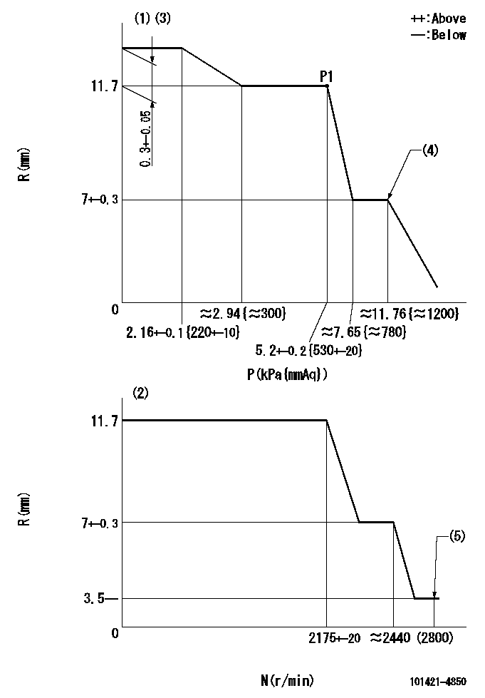
N:Pump speed
R:Rack position (mm)
P:Negative pressure
(1)Pneumatic governor
(2)Mechanical governor
(3)Acting negative pressure: P1
(4)Beginning of idle sub spring operation: L1
(5)Injection quantity Q = Q1 or less
----------
L1=7+-0.3mm Q1=3mm3/st
----------
----------
L1=7+-0.3mm Q1=3mm3/st
----------
Information:
Prior to stopping an engine that is being operated at low loads, run the engine at low speed for 30 seconds before stopping. If the engine has been operating at high load, then it should be run at low speed for three to five minutes to reduce and stabilize internal engine coolant and oil temperatures before stopping. Avoiding hot engine shutdowns will maximize turbocharger shaft and bearing life. Make sure the Engine Stopping procedure is understood. Follow the engine stopping procedure outlined below to allow the engine to cool. Make sure the Engine Stopping procedure is understood. Refer to the Engine Control, Monitoring and Protection topic for information regarding GSC control panel.The engine may be shutdown in several ways. To manually stop the engine, refer to the following information and instructions. The engine is equipped with an Emergency Stop Push Button (ESPB) and an Engine Control Switch (ECS). The ECS has four positions:* OFF/RESET* AUTO* MAN. START* COOLDOWN STOPTo manually stop the engine the Engine Control Switch (ECS) may be turned to the COOLDOWN STOP, AUTOmatic or OFF/RESET positions.Emergency Stop Procedure
Emergency stop controls are for EMERGENCY use ONLY. DO NOT use Emergency Stop Pushbutton (ESPB) for normal stopping procedure. Do NOT start the engine until the problem necessitating the emergency stop has been located and corrected.
The Emergency Stop Pushbutton is located on the front of the control panel. The Emergency Stop Pushbutton will cause immediate shutoff of fuel and/or air. Emergency shutoff controls (including any auxiliary Emergency Stop inputs) should only be used when an emergency exists, and not used to routinely stop the engine. * Emergency stops may be made through the Emergency Stop Pushbutton (ESPB). If the need for emergency engine shutdown occurs, Push the EMERGENCY STOP Pushbutton located on the control panel. This will activate the air and/or fuel shutoffs.* Reset the EMERGENCY STOP Pushbutton (pull out and rotate the button in the direction indicated on the button). Some EMERGENCY STOP Pushbuttons can be pulled out to reset, not requiring any rotation. Manual Fuel Shutoff Lever
A manual shutdown shaft/lever is provided to override the governor control of the engine. This shutdown will only move the fuel control linkage to the fuel OFF position to starve the engine of fuel. The engine will coast to a stop. Be sure to secure any external system components that have been operating to support the engine operation.Manual Stop Procedure
Follow the engine stopping procedure outlined below, to allow the engine to cool. Make sure the Engine Stopping procedure is clearly understood.1. Open the main electrical circuit breaker to remove the load. Lower engine speed with the Manual Speed Potentiometer (MSP) on the control panel. 2. Check the crankcase oil level while the engine is idling. Maintain the oil level between the ADD and FULL marks on the ENGINE AT LOW IDLE WITH WARM OIL side of the dipstick. 3. Adjust all other control systems that must be regulated prior to engine shutoff (voltage regulator, idle/rated switch, etc.). Reduce engine
Have questions with 101421-4850?
Group cross 101421-4850 ZEXEL
Isuzu
101421-4850
9 400 614 079
5156006971
INJECTION-PUMP ASSEMBLY
C190KR
C190KR