Information injection-pump assembly
BOSCH
9 400 614 078
9400614078
ZEXEL
101421-4770
1014214770
ISUZU
5156001204
5156001204

Rating:
Service parts 101421-4770 INJECTION-PUMP ASSEMBLY:
1.
_
6.
COUPLING PLATE
7.
COUPLING PLATE
8.
_
9.
_
11.
Nozzle and Holder
5-15300-067-1
12.
Open Pre:MPa(Kqf/cm2)
11.8{120}
15.
NOZZLE SET
Cross reference number
BOSCH
9 400 614 078
9400614078
ZEXEL
101421-4770
1014214770
ISUZU
5156001204
5156001204
Zexel num
Bosch num
Firm num
Name
9 400 614 078
5156001204 ISUZU
INJECTION-PUMP ASSEMBLY
C190 * K 14BC INJECTION PUMP ASSY PE4A,5A, PE
C190 * K 14BC INJECTION PUMP ASSY PE4A,5A, PE
Calibration Data:
Adjustment conditions
Test oil
1404 Test oil ISO4113 or {SAEJ967d}
1404 Test oil ISO4113 or {SAEJ967d}
Test oil temperature
degC
40
40
45
Nozzle and nozzle holder
105780-8140
Bosch type code
EF8511/9A
Nozzle
105780-0000
Bosch type code
DN12SD12T
Nozzle holder
105780-2080
Bosch type code
EF8511/9
Opening pressure
MPa
17.2
Opening pressure
kgf/cm2
175
Injection pipe
Outer diameter - inner diameter - length (mm) mm 6-2-600
Outer diameter - inner diameter - length (mm) mm 6-2-600
Overflow valve
132424-0620
Overflow valve opening pressure
kPa
157
123
191
Overflow valve opening pressure
kgf/cm2
1.6
1.25
1.95
Tester oil delivery pressure
kPa
157
157
157
Tester oil delivery pressure
kgf/cm2
1.6
1.6
1.6
Direction of rotation (viewed from drive side)
Left L
Left L
Injection timing adjustment
Direction of rotation (viewed from drive side)
Left L
Left L
Injection order
1-3-4-2
Pre-stroke
mm
1.75
1.7
1.8
Beginning of injection position
Drive side NO.1
Drive side NO.1
Difference between angles 1
Cal 1-3 deg. 90 89.5 90.5
Cal 1-3 deg. 90 89.5 90.5
Difference between angles 2
Cal 1-4 deg. 180 179.5 180.5
Cal 1-4 deg. 180 179.5 180.5
Difference between angles 3
Cyl.1-2 deg. 270 269.5 270.5
Cyl.1-2 deg. 270 269.5 270.5
Injection quantity adjustment
Adjusting point
D
Rack position
11.7
Pump speed
r/min
1800
1800
1800
Average injection quantity
mm3/st.
37
36.1
37.9
Max. variation between cylinders
%
0
-2.5
2.5
Basic
*
Fixing the rack
*
Injection quantity adjustment_02
Adjusting point
F
Rack position
7.2+-0.5
Pump speed
r/min
300
300
300
Average injection quantity
mm3/st.
7
5.9
8.1
Max. variation between cylinders
%
0
-14
14
Fixing the rack
*
Injection quantity adjustment_03
Adjusting point
-
Rack position
-
Pump speed
r/min
150
150
150
Average injection quantity
mm3/st.
52
52
Fixing the rack
*
Remarks
Excess fuel for starting.
Excess fuel for starting.
Injection quantity adjustment_04
Adjusting point
-
Rack position
-
Pump speed
r/min
1800
1800
1800
Average injection quantity
mm3/st.
37
36.5
37.5
Remarks
Smoke setting: 4.41 kPa {450 mmAq}
Smoke setting: 4.41 kPa {450 mmAq}
Timer adjustment
Pump speed
r/min
800+-50
Advance angle
deg.
0
0
0
Remarks
Start
Start
Timer adjustment_02
Pump speed
r/min
1100
Advance angle
deg.
1.7
1.2
2.2
Timer adjustment_03
Pump speed
r/min
1500
Advance angle
deg.
4
3.3
4.7
Timer adjustment_04
Pump speed
r/min
1900
Advance angle
deg.
5.3
4.6
6
Timer adjustment_05
Pump speed
r/min
2250
Advance angle
deg.
6.5
6
7
Remarks
Finish
Finish
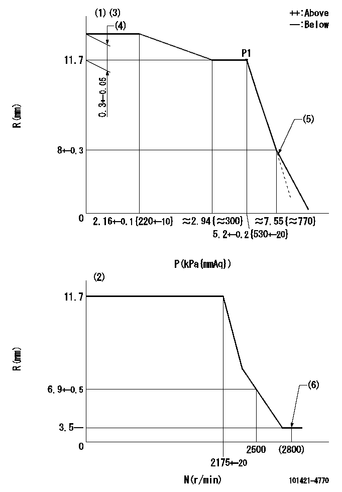
Test data Ex:
Governor adjustment

N:Pump speed
R:Rack position (mm)
P:Negative pressure
(1)Pneumatic governor
(2)Mechanical governor
(3)Acting negative pressure: P1
(4)Torque control stroke
(5)Beginning of idle sub spring operation: L1
(6)Injection quantity Q = Q1 or less
----------
L1=8+-0.3mm Q1=3mm3/st
----------
----------
L1=8+-0.3mm Q1=3mm3/st
----------
Information:
Oil Filters (1), Crankcase Drain (2), Oil Filler (3), Oil Level Gauge (4), Fuel Filters & Priming Pump (5), Air Cleaner with Service Indicator (6), Aftercooler (7), Turbochargers (8), Crankcase Breather with Element (9), Alternator (10), Electronic Governing/Control Module (11), Primary Fuel Filter (12), Oil Cooler (13), Magnetic Speed Sensor (14), Jacket Water Pump (15), Jacket Water Heater (16), Fumes Disposal Drain (17), Ether Canister Bracket (18), Starting Motor (19) and Cooling System Drain (20).
Main Control (GSC) Panel (21), Emergency Stop Pushbutton (22), Engine Control Switch (23), Alarm Module (24).Engine Description
Caterpillar 3412 Generator Set Engines are 27 liter (1649 cu. in.), 137 mm (5.4 in.) bore and 152.4 mm (6.0 in.) stroke, four cycle, 12 cylinder, 65 degree vee diesel design. The engine is available in twin turbocharged or series turbocharged arrangements with jacket water aftercooling and direct fuel injection.The engine and components are designed for high power output. The reduced size and weight plus increased fuel economy provide maximum performance and lower cost per unit of power. The 3412 Generator Set is offered at 1500 rpm, 50 Hz and 1800 rpm, 60 Hz arrangements with various output power ratings. Contact your Caterpillar dealer for information on these power ratings.Larger diameter plungers and a higher injection rate camshaft are incorporated in the valve train/fuel system. The fuel lines are made of high strength steel and the ends of the lines have collared washers to increase reliability. The cooling system has a gear driven centrifugal water pump, two thermostats (one for each bank) which regulate engine coolant temperature, and an oil cooler.The engine lubricating oil, which is both cooled and filtered, is supplied by a gear driven pump. Bypass valves provide unrestricted flow of lubrication oil to engine parts when oil viscosity is high, or either the oil cooler or oil filter elements should become plugged.The 3412 Generator Set Engine is electronically governed and features an exclusive electronic Engine Control Module (ECM). The ECM is a microprocessor-based system that provides full range isochronous speed governing which can operate in speed droop with a zero to ten percent adjustment range.The ECM also provides a cold mode starting strategy, air to fuel ratio control for transient smoke limiting, automatic turbocharger boost pressure and rack position sensor calibration, engine protection and diagnostics.The 3412 engines are equipped with the Electronic Modular Control Panel (EMCP II). The EMCP II is the next generation of engine/generator controls for more accurate, reliable monitoring of engine operating parameters and generator AC voltage metering.The SR4 generator features single bearing, wye connected, brushless, permanent magnet excited designed to match the output characteristics of the engine. These packaged generator sets are designed, manufactured and tested in accordance with ISO 9001 to ensure the highest possible quality on a worldwide basis.Engine efficiency and engine performance and efficiency of emissions controls depend on adherence to proper operation and maintenance recommendations, and the use of recommended fuels, coolants and lubrication oils. To minimize expenses and provide maximum utilization and performance of your
