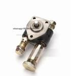
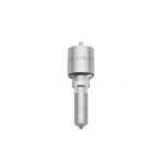
Information injection-pump assembly
BOSCH
9 400 612 608
9400612608
ZEXEL
101405-9350
1014059350
Rating:
Service parts 101405-9350 INJECTION-PUMP ASSEMBLY:
1.
_
5.
AUTOM. ADVANCE MECHANIS
6.
COUPLING PLATE
8.
_
9.
_
11.
Nozzle and Holder
12.
Open Pre:MPa(Kqf/cm2)
21.6{220}
15.
NOZZLE SET
Cross reference number
BOSCH
9 400 612 608
9400612608
ZEXEL
101405-9350
1014059350
Zexel num
Bosch num
Firm num
Name
Calibration Data:
Adjustment conditions
Test oil
1404 Test oil ISO4113 or {SAEJ967d}
1404 Test oil ISO4113 or {SAEJ967d}
Test oil temperature
degC
40
40
45
Nozzle and nozzle holder
105780-8140
Bosch type code
EF8511/9A
Nozzle
105780-0000
Bosch type code
DN12SD12T
Nozzle holder
105780-2080
Bosch type code
EF8511/9
Opening pressure
MPa
17.2
Opening pressure
kgf/cm2
175
Injection pipe
Outer diameter - inner diameter - length (mm) mm 6-2-600
Outer diameter - inner diameter - length (mm) mm 6-2-600
Overflow valve
131424-5720
Overflow valve opening pressure
kPa
255
255
255
Overflow valve opening pressure
kgf/cm2
2.6
2.6
2.6
Tester oil delivery pressure
kPa
255
255
255
Tester oil delivery pressure
kgf/cm2
2.6
2.6
2.6
Direction of rotation (viewed from drive side)
Right R
Right R
Injection timing adjustment
Direction of rotation (viewed from drive side)
Right R
Right R
Injection order
1-3-4-2
Pre-stroke
mm
3.5
3.45
3.55
Rack position
After adjusting injection quantity. R=A
After adjusting injection quantity. R=A
Beginning of injection position
Drive side NO.1
Drive side NO.1
Difference between angles 1
Cal 1-3 deg. 90 89.5 90.5
Cal 1-3 deg. 90 89.5 90.5
Difference between angles 2
Cal 1-4 deg. 180 179.5 180.5
Cal 1-4 deg. 180 179.5 180.5
Difference between angles 3
Cyl.1-2 deg. 270 269.5 270.5
Cyl.1-2 deg. 270 269.5 270.5
Injection quantity adjustment
Adjusting point
A
Rack position
8.4
Pump speed
r/min
900
900
900
Average injection quantity
mm3/st.
75.5
74.5
76.5
Max. variation between cylinders
%
0
-2.5
2.5
Basic
*
Fixing the lever
*
Injection quantity adjustment_02
Adjusting point
C
Rack position
6.7+-0.5
Pump speed
r/min
425
425
425
Average injection quantity
mm3/st.
11.5
10.2
12.8
Max. variation between cylinders
%
0
-10
10
Fixing the rack
*
Injection quantity adjustment_03
Adjusting point
D
Rack position
R1+0.2++
Pump speed
r/min
100
100
100
Average injection quantity
mm3/st.
85
85
90
Fixing the lever
*
Rack limit
*
Test data Ex:
Governor adjustment
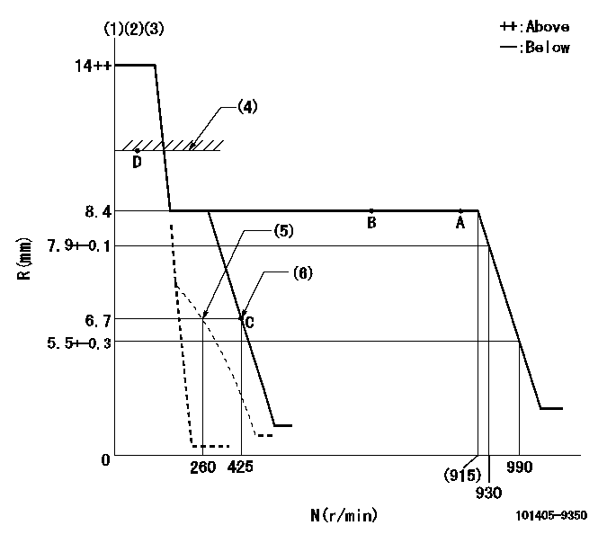
N:Pump speed
R:Rack position (mm)
(1)Target notch: K
(2)Tolerance for racks not indicated: +-0.05mm.
(3)Negative torque control does not operate.
(4)RACK LIMIT
(5)Set idle sub-spring
(6)Main spring setting
----------
K=10
----------
----------
K=10
----------
Speed control lever angle
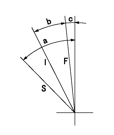
F:Full speed
I:Idle
S:Stop
----------
----------
a=31deg+-3deg b=15deg+-5deg c=2deg+-5deg
----------
----------
a=31deg+-3deg b=15deg+-5deg c=2deg+-5deg
Stop lever angle
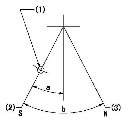
N:Pump normal
S:Stop the pump.
(1)Use the hole at R = aa
(2)Speed = bb, rack position = cc (sealed at delivery)
(3)Normal
----------
aa=25mm bb=0r/min cc=1-0.5mm
----------
a=21deg+-5deg b=(55deg)
----------
aa=25mm bb=0r/min cc=1-0.5mm
----------
a=21deg+-5deg b=(55deg)
0000001501 I/P WITH LOAD PLUNGER ADJ
Load plunger-equipped pump adjustment
1. Adjust the variation between cylinders and the injection quantity.
2. At Full point A, adjust the pre-stroke to the specified value.
3. After pre-stroke adjustment, reconfirm that the fuel injection quantity and the variation between cylinders is as specified.
----------
----------
----------
----------
Timing setting

(1)Pump vertical direction
(2)Position of gear mark '3' at No 1 cylinder's beginning of injection
(3)B.T.D.C.: aa
(4)-
----------
aa=6deg
----------
a=(110deg)
----------
aa=6deg
----------
a=(110deg)
Information:
Overhaul Instructions
If you elect to perform an in-frame overhaul yourself, without having a Caterpillar dealer perform the overhaul for you or without using an overhaul kit, then you should be aware of the following: Rebuild or Exchange Cylinder Head Assembly, Cylinder Packs, Oil Pump and Fuel Transfer PumpYour cylinder head assembly, cylinder packs, oil pump and fuel transfer pump should be inspected according to the instructions found in various Caterpillar reusability publications. Refer to the Index Of Publications On Reusability Or Salvage Of Used Parts section of the Guideline For Reusable Parts and Salvage Operations, form SEBF8029 to determine the reusability publications needed for inspecting your parts.The Guideline For Reusable Parts and Salvage Operations is part of an established Caterpillar parts reusability program. These guidelines were developed to assist Caterpillar dealers and customers reduce costs by avoiding unnecessary expenditures for new parts when existing parts can be used as is, repaired or salvaged. Parts complying with the specifications outlined in the reusable parts guideline will give an additional service life.If your parts comply with the established visual, dimensional, functional, etc., inspection specifications expressed in the reusable parts guideline, then they should be reused.If your parts are not within specification, then they should be salvaged, repaired or replaced. Failure to salvage, repair or replace out-of-spec parts will result in unscheduled downtime and could result in costly repairs caused by potential damage to other engine parts.Furthermore, the use of out-of-spec parts can reduce your engine's efficiency and increase fuel consumption. Reduced engine efficiency and increased fuel consumption translates into higher operating costs. Therefore, Caterpillar recommends that you salvage, repair or replace your out-of-spec parts. Replace Main and Connecting Rod BearingsIn most probability, your main and connecting rod bearings will not last until your second overhaul. Therefore, Caterpillar recommends the installation of new main and connecting rod bearings at each overhaul period. Inspect Crankshaft, Camshaft, Camshaft Followers, Damper, Spacer Plate, Fuel Pump Camshaft and Fuel RackThe ideal time for inspecting your crankshaft, camshaft, camshaft followers, damper, spacer plate, fuel pump camshaft and fuel rack is while your engine is disassembled for overhaul. Inspect each component for potential damage as follows: * Crankshaft - Inspect for bend, journal damage and bearing material seized to the journal. At the same time, check the taper and profile of the crankshaft journals by interpreting your main and connecting rod bearing wear patterns. In case of an out-of-frame overhaul, use the magnetic particle inspection process to check the crankshaft for cracks.* Camshaft - Inspect the camshaft for journal damage. In case of an out-of-frame overhaul, use the magnetic particle inspection process to check the camshaft for cracks.* Camshaft Followers - For out-of-frame overhaul, inspect the cam bearing for fatigue and wear.* Damper - Inspect the damper for rubber deterioration and movement of the outer ring relative to the inner hub. (Refer to the Vibration Damper topic in the PM Level 2 section of this publication for additional information.)* Spacer Plate - Inspect the spacer plate for
If you elect to perform an in-frame overhaul yourself, without having a Caterpillar dealer perform the overhaul for you or without using an overhaul kit, then you should be aware of the following: Rebuild or Exchange Cylinder Head Assembly, Cylinder Packs, Oil Pump and Fuel Transfer PumpYour cylinder head assembly, cylinder packs, oil pump and fuel transfer pump should be inspected according to the instructions found in various Caterpillar reusability publications. Refer to the Index Of Publications On Reusability Or Salvage Of Used Parts section of the Guideline For Reusable Parts and Salvage Operations, form SEBF8029 to determine the reusability publications needed for inspecting your parts.The Guideline For Reusable Parts and Salvage Operations is part of an established Caterpillar parts reusability program. These guidelines were developed to assist Caterpillar dealers and customers reduce costs by avoiding unnecessary expenditures for new parts when existing parts can be used as is, repaired or salvaged. Parts complying with the specifications outlined in the reusable parts guideline will give an additional service life.If your parts comply with the established visual, dimensional, functional, etc., inspection specifications expressed in the reusable parts guideline, then they should be reused.If your parts are not within specification, then they should be salvaged, repaired or replaced. Failure to salvage, repair or replace out-of-spec parts will result in unscheduled downtime and could result in costly repairs caused by potential damage to other engine parts.Furthermore, the use of out-of-spec parts can reduce your engine's efficiency and increase fuel consumption. Reduced engine efficiency and increased fuel consumption translates into higher operating costs. Therefore, Caterpillar recommends that you salvage, repair or replace your out-of-spec parts. Replace Main and Connecting Rod BearingsIn most probability, your main and connecting rod bearings will not last until your second overhaul. Therefore, Caterpillar recommends the installation of new main and connecting rod bearings at each overhaul period. Inspect Crankshaft, Camshaft, Camshaft Followers, Damper, Spacer Plate, Fuel Pump Camshaft and Fuel RackThe ideal time for inspecting your crankshaft, camshaft, camshaft followers, damper, spacer plate, fuel pump camshaft and fuel rack is while your engine is disassembled for overhaul. Inspect each component for potential damage as follows: * Crankshaft - Inspect for bend, journal damage and bearing material seized to the journal. At the same time, check the taper and profile of the crankshaft journals by interpreting your main and connecting rod bearing wear patterns. In case of an out-of-frame overhaul, use the magnetic particle inspection process to check the crankshaft for cracks.* Camshaft - Inspect the camshaft for journal damage. In case of an out-of-frame overhaul, use the magnetic particle inspection process to check the camshaft for cracks.* Camshaft Followers - For out-of-frame overhaul, inspect the cam bearing for fatigue and wear.* Damper - Inspect the damper for rubber deterioration and movement of the outer ring relative to the inner hub. (Refer to the Vibration Damper topic in the PM Level 2 section of this publication for additional information.)* Spacer Plate - Inspect the spacer plate for
