Information injection-pump assembly
BOSCH
9 400 612 358
9400612358
ZEXEL
101405-9240
1014059240
NISSAN-DIESEL
16790NA000
16790na000
Rating:
Service parts 101405-9240 INJECTION-PUMP ASSEMBLY:
1.
_
5.
AUTOM. ADVANCE MECHANIS
6.
COUPLING PLATE
8.
_
9.
_
11.
Nozzle and Holder
1660090105
12.
Open Pre:MPa(Kqf/cm2)
18.1(185)
15.
NOZZLE SET
Cross reference number
BOSCH
9 400 612 358
9400612358
ZEXEL
101405-9240
1014059240
NISSAN-DIESEL
16790NA000
16790na000
Zexel num
Bosch num
Firm num
Name
101405-9240
9 400 612 358
16790NA000 NISSAN-DIESEL
INJECTION-PUMP ASSEMBLY
BD30T K 14BC INJECTION PUMP ASSY PE4A,5A, PE
BD30T K 14BC INJECTION PUMP ASSY PE4A,5A, PE
Calibration Data:
Adjustment conditions
Test oil
1404 Test oil ISO4113 or {SAEJ967d}
1404 Test oil ISO4113 or {SAEJ967d}
Test oil temperature
degC
40
40
45
Nozzle and nozzle holder
105780-8140
Bosch type code
EF8511/9A
Nozzle
105780-0000
Bosch type code
DN12SD12T
Nozzle holder
105780-2080
Bosch type code
EF8511/9
Opening pressure
MPa
17.2
Opening pressure
kgf/cm2
175
Injection pipe
Outer diameter - inner diameter - length (mm) mm 6-2-600
Outer diameter - inner diameter - length (mm) mm 6-2-600
Overflow valve
131424-1520
Overflow valve opening pressure
kPa
157
123
191
Overflow valve opening pressure
kgf/cm2
1.6
1.25
1.95
Tester oil delivery pressure
kPa
157
157
157
Tester oil delivery pressure
kgf/cm2
1.6
1.6
1.6
Direction of rotation (viewed from drive side)
Right R
Right R
Injection timing adjustment
Direction of rotation (viewed from drive side)
Right R
Right R
Injection order
1-3-4-2
Pre-stroke
mm
3.6
3.55
3.65
Beginning of injection position
Drive side NO.1
Drive side NO.1
Difference between angles 1
Cal 1-3 deg. 90 89.5 90.5
Cal 1-3 deg. 90 89.5 90.5
Difference between angles 2
Cal 1-4 deg. 180 179.5 180.5
Cal 1-4 deg. 180 179.5 180.5
Difference between angles 3
Cyl.1-2 deg. 270 269.5 270.5
Cyl.1-2 deg. 270 269.5 270.5
Injection quantity adjustment
Adjusting point
A
Rack position
10.6
Pump speed
r/min
1100
1100
1100
Average injection quantity
mm3/st.
78.5
77.5
79.5
Max. variation between cylinders
%
0
-3.5
3.5
Basic
*
Fixing the lever
*
Boost pressure
kPa
76
76
Boost pressure
mmHg
570
570
Injection quantity adjustment_02
Adjusting point
C
Rack position
8.5+-0.5
Pump speed
r/min
350
350
350
Average injection quantity
mm3/st.
12
10
14
Max. variation between cylinders
%
0
-10
10
Fixing the rack
*
Boost pressure
kPa
0
0
0
Boost pressure
mmHg
0
0
0
Injection quantity adjustment_03
Adjusting point
E
Rack position
10.8++
Pump speed
r/min
100
100
100
Average injection quantity
mm3/st.
70
70
80
Fixing the lever
*
Boost pressure
kPa
0
0
0
Boost pressure
mmHg
0
0
0
Rack limit
*
Boost compensator adjustment
Pump speed
r/min
900
900
900
Rack position
R1-1
Boost pressure
kPa
17.3
12
22.6
Boost pressure
mmHg
130
90
170
Boost compensator adjustment_02
Pump speed
r/min
900
900
900
Rack position
R1(10.6)
Boost pressure
kPa
66.7
64
69.4
Boost pressure
mmHg
500
480
520
Test data Ex:
Governor adjustment
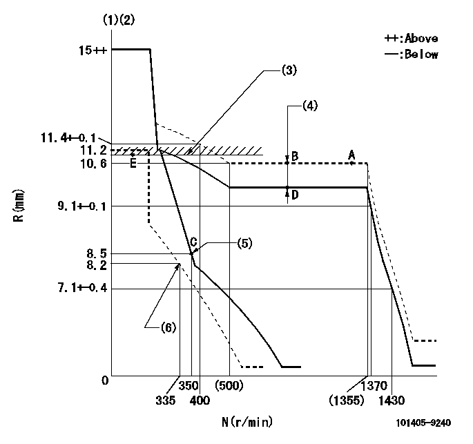
N:Pump speed
R:Rack position (mm)
(1)Target notch: K
(2)Tolerance for racks not indicated: +-0.05mm.
(3)RACK LIMIT
(4)Boost compensator stroke: BCL
(5)Main spring setting
(6)Set idle sub-spring
----------
K=11 BCL=1+-0.1mm
----------
----------
K=11 BCL=1+-0.1mm
----------
Speed control lever angle

F:Full speed
I:Idle
(1)Stopper bolt setting
----------
----------
a=28deg+-5deg b=20deg+-5deg
----------
----------
a=28deg+-5deg b=20deg+-5deg
Stop lever angle

N:Pump normal
S:Stop the pump.
(1)Normal
----------
----------
a=32deg+-5deg b=50deg+-5deg
----------
----------
a=32deg+-5deg b=50deg+-5deg
0000001501 GOV FULL LOAD ADJUSTMENT

Title1:Full load stopper adjustment
Title2:Governor set speed
LABEL1:Distinguishing
LABEL2:Pump speed (r/min)
LABEL3:Ave. injection quantity (mm3/st)
LABEL4:Max. var. bet. cyl.
LABEL5:Remarks
LABEL6:Distinguishing
LABEL7:Governor set speed (r/min)
LABEL8:Maximum no-load speed (r/min)
LABEL9:Remarks
(1)Adjustment conditions are the same as those for measuring injection quantity.
(2)At high idle rack position L
----------
L=7.1mm
----------
a1=A a2=B a3=C a4=- r1=1100r/min r2=1100r/min r3=1100r/min r4=- Q1=- Q2=78.5+-1mm3/st Q3=- Q4=- c1=- c2=+-3.5% c3=- c4=- a5=26 a6=25 a7=24 a8=23 a9=22 a10=21 a11=20 a12=19 a13=- a14=- a15=- r5=1300r/min r6=1250r/min r7=1200r/min r8=1150r/min r9=1100r/min r10=1050r/min r11=1000r/min r12=950r/min r13=- r14=- r15=- R5=1395+-32r/min R6=1340+-31r/min R7=1290+-30r/min R8=1235+-28r/min R9=1180+-27r/min R10=1130+-26r/min R11=1075+-25r/min R12=1020+-23r/min R13=- R14=- R15=-
----------
L=7.1mm
----------
a1=A a2=B a3=C a4=- r1=1100r/min r2=1100r/min r3=1100r/min r4=- Q1=- Q2=78.5+-1mm3/st Q3=- Q4=- c1=- c2=+-3.5% c3=- c4=- a5=26 a6=25 a7=24 a8=23 a9=22 a10=21 a11=20 a12=19 a13=- a14=- a15=- r5=1300r/min r6=1250r/min r7=1200r/min r8=1150r/min r9=1100r/min r10=1050r/min r11=1000r/min r12=950r/min r13=- r14=- r15=- R5=1395+-32r/min R6=1340+-31r/min R7=1290+-30r/min R8=1235+-28r/min R9=1180+-27r/min R10=1130+-26r/min R11=1075+-25r/min R12=1020+-23r/min R13=- R14=- R15=-
Timing setting

(1)Pump vertical direction
(2)Position of gear mark 'ZZ' at No 1 cylinder's beginning of injection
(3)B.T.D.C.: aa
(4)-
----------
aa=10deg
----------
a=(100deg)
----------
aa=10deg
----------
a=(100deg)
Information:
Engine Performance
Poor vehicle performance is traditionally believed to be the result of a lack (or loss) of engine performance, when in fact the engine is only one of numerous factors that influence the overall performance of a vehicle. The previous section on fuel economy describes the factors that determine the power demand on an engine. The engine has no control over the demand made upon it by the vehicle or the operator.A vehicle that requires 225 hp (168 kW) to operate at 55 mph (88 km/h) will get worse fuel economy than a vehicle that requires only 175 hp (130 kW).These same factors also affect the amount of power available to perform additional work such as climb a grade or pass another vehicle. With a 310 hp (231 kW) engine, the first vehicle will have only 85 hp (63 kW) available to perform additional work compared to 135 hp (100 kW) on the second vehicle (mentioned above).If you feel you have a vehicle performance problem, first consider the impact of vehicle efficiency and operating characteristics (vehicle speed, design, etc.), on power demand before questioning engine performance. In the case of poor fuel economy, the engine is not likely to be the cause without the presence of excessive exhaust smoke and/or a significant loss of power.If you feel you have a valid engine performance problem, contact an authorized Caterpillar dealer for assistance. If your engine is under warranty, then the Caterpillar warranty or extended service coverage will cover the cost of resolving a valid engine performance deficiency.However, if the engine is not found at fault, all costs incurred will be the responsibility of the owner.
Adjustment of the fuel system outside Caterpillar specified limits will not improve fuel efficiency and can result in damage to the engine.
Performance Analysis Report (PAR)
PAR complements a good preventive maintenance program and Caterpillar recommends a regularly scheduled PAR analysis to monitor the condition and maintenance requirements of your engine and to ensure your engine is operating at peak efficiency.Potential problems can be identified early, thus preventing unnecessary repair costs and unscheduled downtime. Consult your Caterpillar dealer for complete information and assistance in establishing a PAR program for your engine.PAR reflects the results of various tests normally conducted by your Caterpillar dealer for the purpose of: * confirming your engine is operating efficiently and within specification.* identifying potential problems.* determining components or systems that should be adjusted, replaced, etc.Approximately 80 to 85% of your truck engine's operation and maintenance cost is the cost of the fuel. Therefore, substantial cost reductions can be achieved by keeping your engine operating at peak efficiency. The fuel economy and performance of the engine is affected by the truck specifications, how it is operated and the condition of the engine. Each plays an important part in minimizing your overall owning and operating cost.Caterpillar has an exclusive Performance Analysis Report (PAR) Program that can help you keep the engine portion of this equation up to PAR. The PAR Program uses a chassis
Have questions with 101405-9240?
Group cross 101405-9240 ZEXEL
Yanmar
Nissan-Diesel
101405-9240
9 400 612 358
16790NA000
INJECTION-PUMP ASSEMBLY
BD30T
BD30T