Information injection-pump assembly
BOSCH
9 400 612 829
9400612829
ZEXEL
101405-9230
1014059230
YANMAR
12991651040
12991651040
Rating:
Service parts 101405-9230 INJECTION-PUMP ASSEMBLY:
1.
_

5.
AUTOM. ADVANCE MECHANIS
6.
COUPLING PLATE
7.
COUPLING PLATE
8.
_
9.
_
10.
NOZZLE AND HOLDER ASSY
11.
Nozzle and Holder
12.
Open Pre:MPa(Kqf/cm2)
13.
NOZZLE-HOLDER
14.
NOZZLE
15.
NOZZLE SET
Cross reference number
BOSCH
9 400 612 829
9400612829
ZEXEL
101405-9230
1014059230
YANMAR
12991651040
12991651040
Zexel num
Bosch num
Firm num
Name
Calibration Data:
Adjustment conditions
Test oil
1404 Test oil ISO4113 or {SAEJ967d}
1404 Test oil ISO4113 or {SAEJ967d}
Test oil temperature
degC
40
40
45
Nozzle and nozzle holder
105780-8140
Bosch type code
EF8511/9A
Nozzle
105780-0000
Bosch type code
DN12SD12T
Nozzle holder
105780-2080
Bosch type code
EF8511/9
Opening pressure
MPa
17.2
Opening pressure
kgf/cm2
175
Injection pipe
Outer diameter - inner diameter - length (mm) mm 6-2-600
Outer diameter - inner diameter - length (mm) mm 6-2-600
Overflow valve
131424-1520
Overflow valve opening pressure
kPa
157
157
157
Overflow valve opening pressure
kgf/cm2
1.6
1.6
1.6
Tester oil delivery pressure
kPa
157
157
157
Tester oil delivery pressure
kgf/cm2
1.6
1.6
1.6
Direction of rotation (viewed from drive side)
Right R
Right R
Injection timing adjustment
Direction of rotation (viewed from drive side)
Right R
Right R
Injection order
1-3-4-2
Pre-stroke
mm
3.6
3.55
3.65
Beginning of injection position
Drive side NO.1
Drive side NO.1
Difference between angles 1
Cal 1-3 deg. 90 89.5 90.5
Cal 1-3 deg. 90 89.5 90.5
Difference between angles 2
Cal 1-4 deg. 180 179.5 180.5
Cal 1-4 deg. 180 179.5 180.5
Difference between angles 3
Cyl.1-2 deg. 270 269.5 270.5
Cyl.1-2 deg. 270 269.5 270.5
Injection quantity adjustment
Adjusting point
A
Rack position
9
Pump speed
r/min
800
800
800
Average injection quantity
mm3/st.
44.7
43.7
45.7
Max. variation between cylinders
%
0
-2.5
2.5
Basic
*
Fixing the lever
*
Injection quantity adjustment_02
Adjusting point
C
Rack position
6.8+-0.5
Pump speed
r/min
450
450
450
Average injection quantity
mm3/st.
13
12
14
Max. variation between cylinders
%
0
-15
15
Fixing the rack
*
Injection quantity adjustment_03
Adjusting point
D
Rack position
9.5++
Pump speed
r/min
100
100
100
Average injection quantity
mm3/st.
65
65
70
Fixing the lever
*
Rack limit
*
Test data Ex:
Governor adjustment
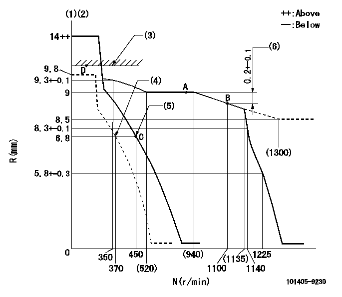
N:Pump speed
R:Rack position (mm)
(1)Target notch: K
(2)Tolerance for racks not indicated: +-0.05mm.
(3)RACK LIMIT
(4)Set idle sub-spring
(5)Main spring setting
(6)Rack difference between N = N1 and N = N2
----------
K=10 N1=1100r/min N2=800r/min
----------
----------
K=10 N1=1100r/min N2=800r/min
----------
Speed control lever angle

F:Full speed
I:Idle
(1)Stopper bolt setting
----------
----------
a=5deg+-5deg b=22deg+-5deg
----------
----------
a=5deg+-5deg b=22deg+-5deg
Stop lever angle
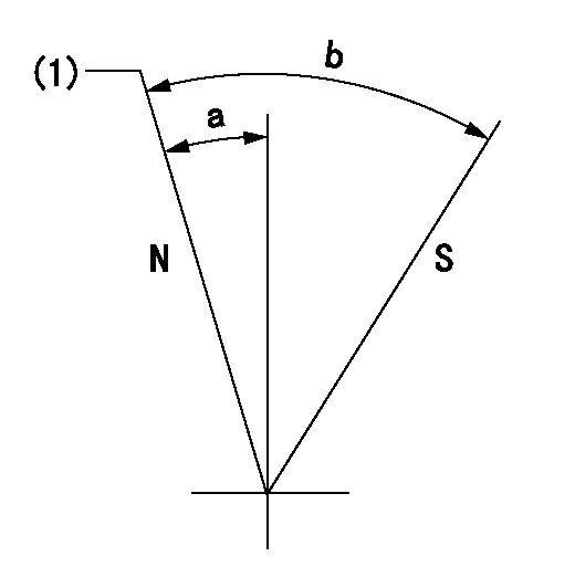
N:Pump normal
S:Stop the pump.
(1)Normal
----------
----------
a=7deg+-5deg b=53deg+-5deg
----------
----------
a=7deg+-5deg b=53deg+-5deg
Timing setting

(1)Pump vertical direction
(2)Position of camshaft's key groove at No 1 cylinder's beginning of injection
(3)-
(4)-
----------
----------
a=(60deg)
----------
----------
a=(60deg)
Information:
Exhaust brakes should not be used as a primary or service brake.
Auxiliary engine braking devices are approved for use on the 3406B PEEC Engine.Compression Brake
Operation (Jacobs Brake or Pacific Brake)
The Jacobs Engine Brake should not be used as a primary or service brake. Do not allow the engine to exceed 2300 rpm. However, engines equipped with a Jacobs Engine Brake should not normally be operated above 2100 rpm.
The Jacobs Engine Brake is an engine attachment that converts a diesel engine into an air compressor. Its function is to slow the vehicle and reduce brake wear.Operating Controls-Compression Brake
The Jacobs Engine Brake controls may include a dash mounted module or an ON/OFF switch and a three position switch with "Lo" and "Hi" depending on how many cylinders of braking desired. Refer to the OEM vehicle manual for the type of operating controls that your vehicle is equipped with.The PEEC ECM monitors the clutch, brake, throttle position and engine rpm to determine when the Jacobs Brake can operate. It may take up to two seconds before Jacobs Brake activates.Since the Jacobs Engine Brake is most effective at rated engine rpm, gear selection is very important. Gearing down the vehicle, within the limits of rated engine rpm, makes the engine brake a more effective retarder. Maximum retarding occurs at higher engine rpm.Cruise Control (If Equipped) OFF
With the Cruis Control (CC) in the OFF position the Jacobs Engine Brake will function like any vehicle and engine that is not equipped with Cruise Control (CC).Cruise Control (If Equipped) ON
The driver must apply the service brake approximately two seconds and then release the service brake pedal. If the retarder "Latch" mode has been programmed, the retarder will continue to slow the vehicle. To release or deactivate the retarder, the clutch or throttle foot pedal must be depressed or the engine rpm drop to 950 rpm.When using "Coast" mode, the Jacobs Brake should activate within two seconds after the brake pedal is applied and remain on as long as the brake pedal is applied. At the time the brake pedal is applied, the Cruise Control (CC) will deactivate.For information on adjustment to Jacobs Brake slave piston lash, refer to PM Level 2-Engine Valve Lash. Refer to Jacobs Brake Troubleshooting Manual, Form SENR4251 for information regarding this auxiliary braking system.There are differences in exhaust braking devices from those with little or no leakage when activated to those with a great deal of leakage.Sliding Gate Type (Williams Blue Ox)
This type of exhaust brake allows minimal leakage and must have a relief orifice to limit the maximum exhaust manifold back pressure to 50 psi (345 kPa) at maximum engine braking rpm. Flapper Type (Pacific)
With this type of exhaust brake, there is usually leakage around the movable plate. To obtain 50 psi (345 kPa) or 70 psi (485 kPa) performance level braking, a small hole would likely be required. The maximum permissible exhaust back pressure at maximum engine braking rpm is measured at the 1/4 NPT hole in the exhaust