Information injection-pump assembly
BOSCH
9 400 612 824
9400612824
ZEXEL
101405-9200
1014059200
YANMAR
12998351000
12998351000
Rating:
Service parts 101405-9200 INJECTION-PUMP ASSEMBLY:
1.
_

5.
AUTOM. ADVANCE MECHANIS
6.
COUPLING PLATE
7.
COUPLING PLATE
8.
_
9.
_
10.
NOZZLE AND HOLDER ASSY
11.
Nozzle and Holder
12.
Open Pre:MPa(Kqf/cm2)
13.
NOZZLE-HOLDER
14.
NOZZLE
15.
NOZZLE SET
Cross reference number
BOSCH
9 400 612 824
9400612824
ZEXEL
101405-9200
1014059200
YANMAR
12998351000
12998351000
Zexel num
Bosch num
Firm num
Name
Calibration Data:
Adjustment conditions
Test oil
1404 Test oil ISO4113 or {SAEJ967d}
1404 Test oil ISO4113 or {SAEJ967d}
Test oil temperature
degC
40
40
45
Nozzle and nozzle holder
105780-8140
Bosch type code
EF8511/9A
Nozzle
105780-0000
Bosch type code
DN12SD12T
Nozzle holder
105780-2080
Bosch type code
EF8511/9
Opening pressure
MPa
17.2
Opening pressure
kgf/cm2
175
Injection pipe
Outer diameter - inner diameter - length (mm) mm 6-2-600
Outer diameter - inner diameter - length (mm) mm 6-2-600
Overflow valve
131424-1520
Overflow valve opening pressure
kPa
157
157
157
Overflow valve opening pressure
kgf/cm2
1.6
1.6
1.6
Tester oil delivery pressure
kPa
157
157
157
Tester oil delivery pressure
kgf/cm2
1.6
1.6
1.6
Direction of rotation (viewed from drive side)
Right R
Right R
Injection timing adjustment
Direction of rotation (viewed from drive side)
Right R
Right R
Injection order
1-3-4-2
Pre-stroke
mm
3.6
3.1
4.1
Beginning of injection position
Drive side NO.1
Drive side NO.1
Difference between angles 1
Cal 1-3 deg. 90 89.5 90.5
Cal 1-3 deg. 90 89.5 90.5
Difference between angles 2
Cal 1-4 deg. 180 179.5 180.5
Cal 1-4 deg. 180 179.5 180.5
Difference between angles 3
Cyl.1-2 deg. 270 269.5 270.5
Cyl.1-2 deg. 270 269.5 270.5
Injection quantity adjustment
Adjusting point
A
Rack position
10.2
Pump speed
r/min
1250
1250
1250
Average injection quantity
mm3/st.
66
65
67
Max. variation between cylinders
%
0
-2.5
2.5
Basic
*
Fixing the lever
*
Injection quantity adjustment_02
Adjusting point
C
Rack position
7.6+-0.5
Pump speed
r/min
400
400
400
Average injection quantity
mm3/st.
13
12
14
Max. variation between cylinders
%
0
-15
15
Fixing the rack
*
Injection quantity adjustment_03
Adjusting point
D
Rack position
11.2++
Pump speed
r/min
100
100
100
Average injection quantity
mm3/st.
85
80
90
Fixing the lever
*
Rack limit
*
Test data Ex:
Governor adjustment
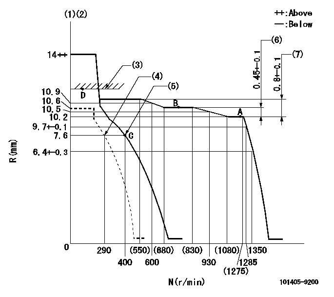
N:Pump speed
R:Rack position (mm)
(1)Target notch: K
(2)Tolerance for racks not indicated: +-0.05mm.
(3)RACK LIMIT
(4)Set idle sub-spring
(5)Main spring setting
(6)Rack difference between N = N1 and N = N2
(7)Rack difference between N = N3 and N = N4
----------
K=12 N1=1250r/min N2=800r/min N3=1250r/min N4=450r/min
----------
----------
K=12 N1=1250r/min N2=800r/min N3=1250r/min N4=450r/min
----------
Speed control lever angle

F:Full speed
I:Idle
(1)Stopper bolt setting
----------
----------
a=16deg+-5deg b=30deg+-5deg
----------
----------
a=16deg+-5deg b=30deg+-5deg
Stop lever angle
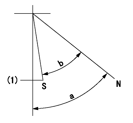
N:Pump normal
S:Stop the pump.
(1)Normal stop
----------
----------
a=58deg+-5deg b=53deg+-5deg
----------
----------
a=58deg+-5deg b=53deg+-5deg
Timing setting

(1)Pump vertical direction
(2)Position of camshaft's key groove at No 1 cylinder's beginning of injection
(3)-
(4)-
----------
----------
a=(60deg)
----------
----------
a=(60deg)
Information:
Your truck may not have the same or all of the gauges as shown in the illustrations. The illustrations shown are of typical gauges.Gauges provide a "look" inside the engine. Be sure they are in good working order. You can determine what is the "normal" operating range by observing your gauges over a period of time.Noticeable changes in gauge readings are indicative of potential gauge or engine problems. This also applies to gauge readings that have changed significantly but are still within specifications. The cause of any sudden or significant change in the readings should be determined and corrected. Contact your Caterpillar dealer for assistance as needed. Oil Pressure - Indicates engine oil pressure. The oil pressure should be between 40 and 88 psi (275 and 606 kPa) when the engine is running at rated engine speed, with SAE 15W-40 oil, at operating temperature. A lower pressure is normal at low idling speed.The "Check Engine" light will come on and a fault logged in the ECM system if oil pressure drops below 5 psi (35 kPa) at low idle rpm.
If no oil pressure is indicated, stop the engine. Engine damage can result.
Water Temperature - Indicates engine coolant temperature. It should normally indicate between 170°F (77°C) and 208°F (98°C). Maximum allowable temperature is 210°F (99°C) with the cooling system pressurized. Somewhat higher temperatures may occur under certain conditions. Ammeter - Indicates the amount of charge or discharge in the battery charging circuit. Normal operation of the indicator should be slightly to the positive (right) side of "0" (zero).With the engine running, during normal operation, if the indicator is constantly to the negative (left) side of "0" (zero) or shows excessive charge, have the charging system checked for malfunction. Tachometer - Indicates engine rpm (speed). The engine can be operated at high idle without damage, but should not be allowed to overspeed. Overspeeding when downshifting, going downhill, etc., can result in serious damage to your engine.
Do not exceed 2300 rpm in any situation.
Fuel Level - Indicates fuel level in the fuel tank. Electrically operated, it registers only when the key switch is ON. Fuel Pressure - Indicates fuel pressure to the injection pump. The indicator should register in the NORMAL (green) range.If the indicator moves to the OUT position or registers below 23 psi (160 kPa) when equipped with a numerical gauge, the engine will not operate properly. A drop in fuel pressure usually indicates a dirty or plugged fuel filter. Service Hour Meter - Indicates the total number of clock hours the engine has operated.