Information injection-pump assembly
BOSCH
9 400 612 606
9400612606
ZEXEL
101405-9180
1014059180
YANMAR
12391551000
12391551000

Rating:
Service parts 101405-9180 INJECTION-PUMP ASSEMBLY:
1.
_

5.
AUTOM. ADVANCE MECHANIS
6.
COUPLING PLATE
7.
COUPLING PLATE
8.
_
9.
_
10.
NOZZLE AND HOLDER ASSY
11.
Nozzle and Holder
12.
Open Pre:MPa(Kqf/cm2)
13.
NOZZLE-HOLDER
14.
NOZZLE
15.
NOZZLE SET
Cross reference number
BOSCH
9 400 612 606
9400612606
ZEXEL
101405-9180
1014059180
YANMAR
12391551000
12391551000
Zexel num
Bosch num
Firm num
Name
101405-9180
9 400 612 606
12391551000 YANMAR
INJECTION-PUMP ASSEMBLY
4TNE106 K 14BC INJECTION PUMP ASSY PE4A,5A, PE
4TNE106 K 14BC INJECTION PUMP ASSY PE4A,5A, PE
Calibration Data:
Adjustment conditions
Test oil
1404 Test oil ISO4113 or {SAEJ967d}
1404 Test oil ISO4113 or {SAEJ967d}
Test oil temperature
degC
40
40
45
Nozzle and nozzle holder
105780-8140
Bosch type code
EF8511/9A
Nozzle
105780-0000
Bosch type code
DN12SD12T
Nozzle holder
105780-2080
Bosch type code
EF8511/9
Opening pressure
MPa
17.2
Opening pressure
kgf/cm2
175
Injection pipe
Outer diameter - inner diameter - length (mm) mm 6-2-600
Outer diameter - inner diameter - length (mm) mm 6-2-600
Overflow valve
131424-1520
Overflow valve opening pressure
kPa
157
123
191
Overflow valve opening pressure
kgf/cm2
1.6
1.25
1.95
Tester oil delivery pressure
kPa
157
157
157
Tester oil delivery pressure
kgf/cm2
1.6
1.6
1.6
Direction of rotation (viewed from drive side)
Right R
Right R
Injection timing adjustment
Direction of rotation (viewed from drive side)
Right R
Right R
Injection order
1-3-4-2
Pre-stroke
mm
3.3
3.25
3.35
Beginning of injection position
Drive side NO.1
Drive side NO.1
Difference between angles 1
Cal 1-3 deg. 90 89.5 90.5
Cal 1-3 deg. 90 89.5 90.5
Difference between angles 2
Cal 1-4 deg. 180 179.5 180.5
Cal 1-4 deg. 180 179.5 180.5
Difference between angles 3
Cyl.1-2 deg. 270 269.5 270.5
Cyl.1-2 deg. 270 269.5 270.5
Injection quantity adjustment
Adjusting point
A
Rack position
10.7
Pump speed
r/min
1250
1250
1250
Average injection quantity
mm3/st.
73.5
72.5
74.5
Max. variation between cylinders
%
0
-2.5
2.5
Basic
*
Fixing the lever
*
Injection quantity adjustment_02
Adjusting point
C
Rack position
7.6+-0.5
Pump speed
r/min
550
550
550
Average injection quantity
mm3/st.
13
12
14
Max. variation between cylinders
%
0
-15
15
Fixing the rack
*
Injection quantity adjustment_03
Adjusting point
D
Rack position
11.6++
Pump speed
r/min
100
100
100
Average injection quantity
mm3/st.
100
95
105
Fixing the lever
*
Rack limit
*
Test data Ex:
Governor adjustment
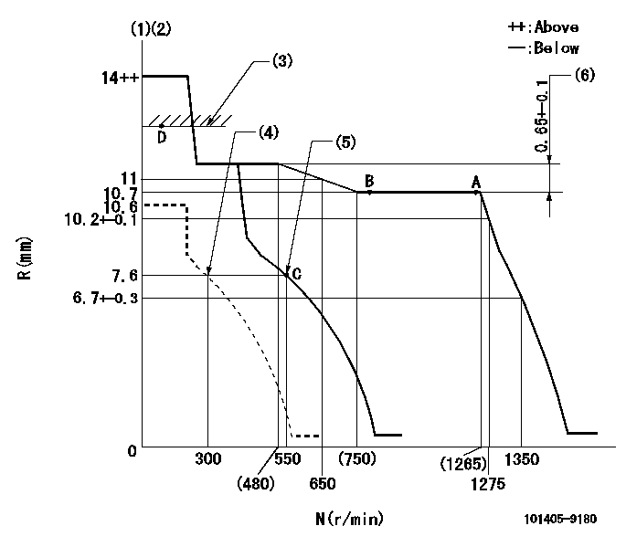
N:Pump speed
R:Rack position (mm)
(1)Target notch: K
(2)Tolerance for racks not indicated: +-0.05mm.
(3)RACK LIMIT
(4)Set idle sub-spring
(5)Main spring setting
(6)Rack difference between N = N1 and N = N2
----------
K=12 N1=1250r/min N2=400r/min
----------
----------
K=12 N1=1250r/min N2=400r/min
----------
Speed control lever angle
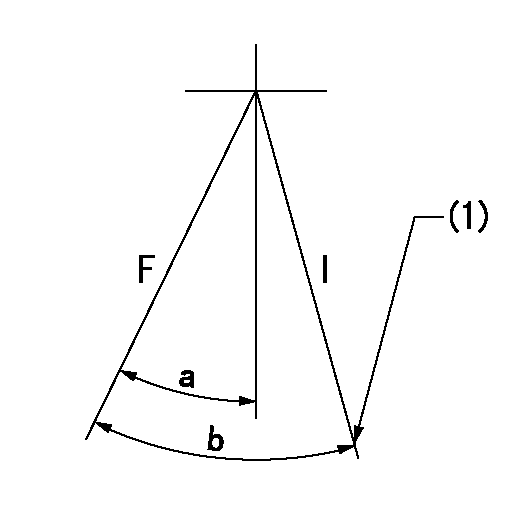
F:Full speed
I:Idle
(1)Stopper bolt setting
----------
----------
a=17deg+-5deg b=26deg+-5deg
----------
----------
a=17deg+-5deg b=26deg+-5deg
Stop lever angle
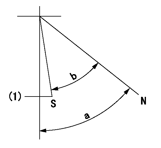
N:Pump normal
S:Stop the pump.
(1)Normal stop
----------
----------
a=58deg+-5deg b=53deg+-5deg
----------
----------
a=58deg+-5deg b=53deg+-5deg
Timing setting

(1)Pump vertical direction
(2)Position of camshaft's key groove at No 1 cylinder's beginning of injection
(3)-
(4)-
----------
----------
a=(60deg)
----------
----------
a=(60deg)
Information:
Fluid Penetration
Always use a board or cardboard when checking for a leak. Escaping fluid under pressure, even a pin-hole size leak, can penetrate body tissue, causing serious injury, and possible death.If fluid is injected into your skin, it must be treated by a doctor familiar with this type of injury immediately.Asbestos Information
Caution should be used to avoid breathing dust that may be generated when handling components containing asbestos fibers. If this dust is inhaled, it can be hazardous to your health.Components in Caterpillar products that may contain asbestos fibers are brake pads, brake band and lining assemblies, clutch plates and some gaskets.The asbestos used in these components is usually bound in a resin or sealed in some way. Normal handling is not hazardous as long as airborne dust which contains asbestos is not generated.If dust which may contain asbestos is present, there are several common sense guidelines that should be followed.* Never use compressed air for cleaning.* Avoid brushing or grinding of asbestos containing materials.* For clean up, use wet methods or a vacuum equipped with a high efficiency particulate air (HEPA) filter.* Use exhaust ventilation on permanent machining jobs.* Wear an approved respirator if there is no other way to control the dust.* Comply with applicable rules and regulations for the work place (for example in the U.S.A., OSHA requirements as set forth in 29 CFR 1910.1001).* Follow environmental rules and regulations for disposal of asbestos.* Avoid areas where asbestos particles may be in the air.Lines, Tubes and Hoses
Do not bend or strike high pressure lines. Do not install bent or damaged lines, tubes or hoses.Repair any loose or damaged fuel and oil lines, tubes and hoses. Leaks can cause fires.Inspect all lines, tubes and hoses carefully. Do not use your bare hands to check for leaks. Tighten all connections to the recommended torque.* End fittings damaged or leaking.* Outer covering chafed or cut and wire reinforcing exposed.* Outer covering ballooning locally.* Evidence of kinking or crushing of the flexible part of the hose.* Armoring embedded in the outer cover.* End fittings displaced.Burn Prevention
Do not touch any part of an operating engine. Allow the engine to cool before any repairs are performed on the engine.Relieve all pressure in air, oil, fuel or cooling systems before any lines, fittings or related items are disconnected or removed.Coolant
To prevent personal injury, do not step up on engine to remove the filler cap, if applicable. Use an adequate ladder.At operating temperature, the engine coolant is hot and under pressure. The radiator and all lines to heaters or the engine contain hot water. When pressure is relieved rapidly, this hot water can turn into steam.Any contact with hot water or steam can cause severe burns.Check the coolant level only after the engine has been stopped and the filler cap is cool enough to remove with your bare hand.Remove the cooling system filler cap slowly to relieve pressure.Supplemental cooling system additive contains alkali. To prevent personal injury, avoid contact with the skin and
Have questions with 101405-9180?
Group cross 101405-9180 ZEXEL
Yanmar
Mitsubishi-Heav
Mitsubishi-Heav
Mitsubishi-Heav
Mitsubishi-Heav
Mitsubishi-Heav
Yanmar
101405-9180
9 400 612 606
12391551000
INJECTION-PUMP ASSEMBLY
4TNE106
4TNE106