Information injection-pump assembly
BOSCH
9 400 612 820
9400612820
ZEXEL
101405-9041
1014059041
Rating:
Service parts 101405-9041 INJECTION-PUMP ASSEMBLY:
1.
_

5.
AUTOM. ADVANCE MECHANIS
6.
COUPLING PLATE
7.
COUPLING PLATE
8.
_
9.
_
10.
NOZZLE AND HOLDER ASSY
11.
Nozzle and Holder
12.
Open Pre:MPa(Kqf/cm2)
13.
NOZZLE-HOLDER
14.
NOZZLE
15.
NOZZLE SET
Cross reference number
BOSCH
9 400 612 820
9400612820
ZEXEL
101405-9041
1014059041
Zexel num
Bosch num
Firm num
Name
Calibration Data:
Adjustment conditions
Test oil
1404 Test oil ISO4113 or {SAEJ967d}
1404 Test oil ISO4113 or {SAEJ967d}
Test oil temperature
degC
40
40
45
Nozzle and nozzle holder
105780-8140
Bosch type code
EF8511/9A
Nozzle
105780-0000
Bosch type code
DN12SD12T
Nozzle holder
105780-2080
Bosch type code
EF8511/9
Opening pressure
MPa
17.2
Opening pressure
kgf/cm2
175
Injection pipe
Outer diameter - inner diameter - length (mm) mm 6-2-600
Outer diameter - inner diameter - length (mm) mm 6-2-600
Overflow valve
131424-1520
Overflow valve opening pressure
kPa
157
157
157
Overflow valve opening pressure
kgf/cm2
1.6
1.6
1.6
Tester oil delivery pressure
kPa
157
157
157
Tester oil delivery pressure
kgf/cm2
1.6
1.6
1.6
Direction of rotation (viewed from drive side)
Right R
Right R
Injection timing adjustment
Direction of rotation (viewed from drive side)
Right R
Right R
Injection order
1-3-4-2
Pre-stroke
mm
3.6
3.55
3.65
Beginning of injection position
Drive side NO.1
Drive side NO.1
Difference between angles 1
Cal 1-3 deg. 90 89.5 90.5
Cal 1-3 deg. 90 89.5 90.5
Difference between angles 2
Cal 1-4 deg. 180 179.5 180.5
Cal 1-4 deg. 180 179.5 180.5
Difference between angles 3
Cyl.1-2 deg. 270 269.5 270.5
Cyl.1-2 deg. 270 269.5 270.5
Injection quantity adjustment
Adjusting point
A
Rack position
10.2
Pump speed
r/min
1250
1250
1250
Average injection quantity
mm3/st.
66
65
67
Max. variation between cylinders
%
0
-2.5
2.5
Basic
*
Fixing the lever
*
Injection quantity adjustment_02
Adjusting point
C
Rack position
7.6+-0.5
Pump speed
r/min
400
400
400
Average injection quantity
mm3/st.
13
12
14
Max. variation between cylinders
%
0
-15
15
Fixing the rack
*
Injection quantity adjustment_03
Adjusting point
D
Rack position
11.2++
Pump speed
r/min
100
100
100
Average injection quantity
mm3/st.
85
80
90
Fixing the lever
*
Rack limit
*
Test data Ex:
Governor adjustment
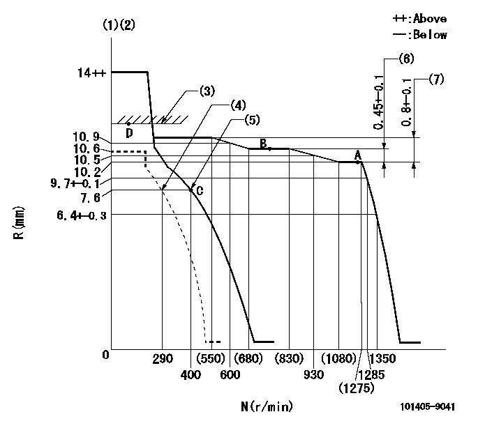
N:Pump speed
R:Rack position (mm)
(1)Target notch: K
(2)Tolerance for racks not indicated: +-0.05mm.
(3)RACK LIMIT
(4)Set idle sub-spring
(5)Main spring setting
(6)Rack difference between N = N1 and N = N2
(7)Rack difference between N = N3 and N = N4
----------
K=12 N1=1250r/min N2=800r/min N3=1250r/min N4=450r/min
----------
----------
K=12 N1=1250r/min N2=800r/min N3=1250r/min N4=450r/min
----------
Speed control lever angle

F:Full speed
I:Idle
(1)Stopper bolt setting
----------
----------
a=16deg+-5deg b=30deg+-5deg
----------
----------
a=16deg+-5deg b=30deg+-5deg
Stop lever angle
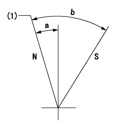
N:Pump normal
S:Stop the pump.
(1)Normal
----------
----------
a=7deg+-5deg b=53deg+-5deg
----------
----------
a=7deg+-5deg b=53deg+-5deg
Timing setting

(1)Pump vertical direction
(2)Position of camshaft's key groove at No 1 cylinder's beginning of injection
(3)-
(4)-
----------
----------
a=(60deg)
----------
----------
a=(60deg)
Information:
The BrakeSaver should not be used as a primary or service brake. The BrakeSaver is not an emergency or quick stop brake. Use the service brakes for quick stops.
No special skills are required to operate a vehicle with a BrakeSaver. However, it requires the operator to watch the engine speed and the BrakeSaver oil temperature.The BrakeSaver provides auxiliary braking to slow the truck and to control speed on long grades. Governing the deceleration or downhill speed of a vehicle by using the BrakeSaver results in reduced wear on brake linings and brake drums. It helps save the service brakes for emergency stopping requirements.Braking effort is a direct function of engine speed. The greater the engine speed the greater the braking effort. This applies to all engines, especially those with slower speed economy ratings.The BrakeSaver utilizes the engine oil and cooling systems, which eliminates the need for additional oil or cooling systems.Scheduled maintenance on the BrakeSaver, or additional engine maintenance, is not required.Trucks equipped with the BrakeSaver require an additional amount of engine lubricating oil. See the Refill Capacities chart in this publication for proper amount of oil required for a BrakeSaver equipped engine. MANUAL CONTROL: The hand operated control lever is usually mounted on the steering column. It provides a smooth modulated application of the BrakeSaver for desired retarding of the vehicle up to 2300 engine rpm. This controlled modulation of the BrakeSaver is especially desirable on slippery roads. Increasing or decreasing the BrakeSaver action is accomplished by moving the control lever. AUTOMATIC CONTROL: The mode selector switch must be in the AUTOMATIC MANUAL position for automatic control. In this mode, the BrakeSaver will automatically be applied when the clutch is engaged and the accelerator pedal is released.The BrakeSaver will automatically shut off when the clutch is disengaged or when the accelerator pedal is depressed. It will engage again when the clutch is reengaged and the accelerator pedal is released. GAUGES: The BrakeSaver CONTROL AIR PRESSURE gauge indicates the pressure at the BrakeSaver control valve. Air pressure should not exceed 50 psi (345 kPa).If the indicator shows reduced or no pressure, the BrakeSaver may not provide any braking effort. Stop the vehicle or operate at a reduced speed. Control vehicle stopping with proper downshifting and service brakes until proper repairs are made.The BrakeSaver oil temperature gauge indicator should register in the NORMAL (green) range. If the indicator moves to the red range, move the BrakeSaver manual control lever to the OFF position.Operate the vehicle with the service brakes only, or stop the vehicle and let the engine idle until the oil temperature registers in the NORMAL range.
Do not exceed 239°F (115°C) maximum engine oil temperature at any time. Do not exceed 2300 rpm in any situation. Overspeeding can result in serious damage to your engine.
For maximum BrakeSaver effectiveness, select the proper gearing to keep the engine rpm as close to 2300 rpm as possible without exceeding 2300 rpm. BrakeSaver effort declines as rpm goes down.Manual operation adds modulation