Information injection-pump assembly
BOSCH
9 400 611 821
9400611821
ZEXEL
101405-9040
1014059040

Rating:
Service parts 101405-9040 INJECTION-PUMP ASSEMBLY:
1.
_

5.
AUTOM. ADVANCE MECHANIS
6.
COUPLING PLATE
7.
COUPLING PLATE
8.
_
9.
_
10.
NOZZLE AND HOLDER ASSY
11.
Nozzle and Holder
12.
Open Pre:MPa(Kqf/cm2)
13.
NOZZLE-HOLDER
14.
NOZZLE
15.
NOZZLE SET
Cross reference number
BOSCH
9 400 611 821
9400611821
ZEXEL
101405-9040
1014059040
Zexel num
Bosch num
Firm num
Name
Calibration Data:
Adjustment conditions
Test oil
1404 Test oil ISO4113 or {SAEJ967d}
1404 Test oil ISO4113 or {SAEJ967d}
Test oil temperature
degC
40
40
45
Nozzle and nozzle holder
105780-8140
Bosch type code
EF8511/9A
Nozzle
105780-0000
Bosch type code
DN12SD12T
Nozzle holder
105780-2080
Bosch type code
EF8511/9
Opening pressure
MPa
17.2
Opening pressure
kgf/cm2
175
Injection pipe
Outer diameter - inner diameter - length (mm) mm 6-2-600
Outer diameter - inner diameter - length (mm) mm 6-2-600
Overflow valve
131424-1520
Overflow valve opening pressure
kPa
157
123
191
Overflow valve opening pressure
kgf/cm2
1.6
1.25
1.95
Tester oil delivery pressure
kPa
157
157
157
Tester oil delivery pressure
kgf/cm2
1.6
1.6
1.6
Direction of rotation (viewed from drive side)
Right R
Right R
Injection timing adjustment
Direction of rotation (viewed from drive side)
Right R
Right R
Injection order
1-3-4-2
Pre-stroke
mm
3.6
3.55
3.65
Beginning of injection position
Drive side NO.1
Drive side NO.1
Difference between angles 1
Cal 1-3 deg. 90 89.5 90.5
Cal 1-3 deg. 90 89.5 90.5
Difference between angles 2
Cal 1-4 deg. 180 179.5 180.5
Cal 1-4 deg. 180 179.5 180.5
Difference between angles 3
Cyl.1-2 deg. 270 269.5 270.5
Cyl.1-2 deg. 270 269.5 270.5
Injection quantity adjustment
Adjusting point
A
Rack position
10.2
Pump speed
r/min
1250
1250
1250
Average injection quantity
mm3/st.
66
65
67
Max. variation between cylinders
%
0
-2.5
2.5
Basic
*
Fixing the lever
*
Injection quantity adjustment_02
Adjusting point
C
Rack position
7.6+-0.5
Pump speed
r/min
400
400
400
Average injection quantity
mm3/st.
13
12
14
Max. variation between cylinders
%
0
-15
15
Fixing the rack
*
Injection quantity adjustment_03
Adjusting point
D
Rack position
-
Pump speed
r/min
100
100
100
Average injection quantity
mm3/st.
85
80
90
Fixing the lever
*
Rack limit
*
Test data Ex:
Governor adjustment
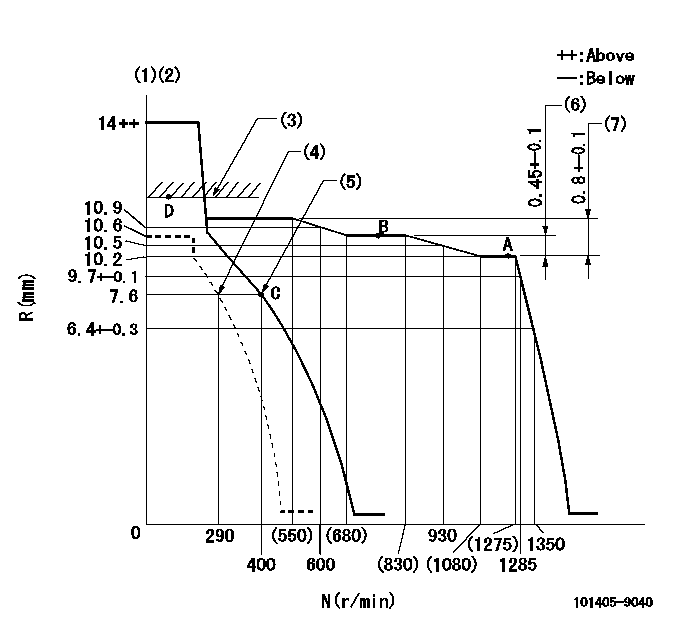
N:Pump speed
R:Rack position (mm)
(1)Target notch: K
(2)Tolerance for racks not indicated: +-0.05mm.
(3)RACK LIMIT
(4)Set idle sub-spring
(5)Main spring setting
(6)Rack difference between N = N1 and N = N2
(7)Rack difference between N = N3 and N = N4
----------
K=12 N1=1250r/min N2=800r/min N3=1250r/min N4=450r/min
----------
----------
K=12 N1=1250r/min N2=800r/min N3=1250r/min N4=450r/min
----------
Speed control lever angle

F:Full speed
I:Idle
(1)Stopper bolt setting
----------
----------
a=16deg+-5deg b=30deg+-5deg
----------
----------
a=16deg+-5deg b=30deg+-5deg
Stop lever angle
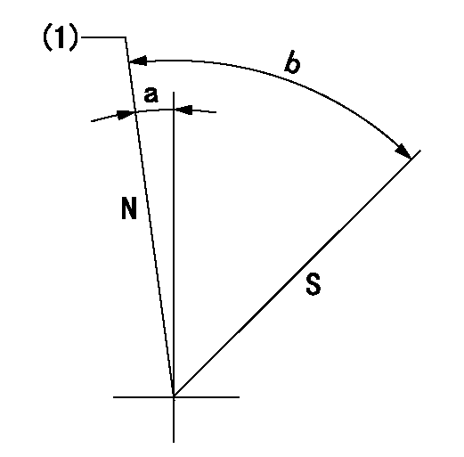
N:Pump normal
S:Stop the pump.
(1)Normal
----------
----------
a=7deg+-5deg b=53deg+-5deg
----------
----------
a=7deg+-5deg b=53deg+-5deg
Timing setting

(1)Pump vertical direction
(2)Position of camshaft's key groove at No 1 cylinder's beginning of injection
(3)-
(4)-
----------
----------
a=(60deg)
----------
----------
a=(60deg)
Information:
Proper operation and maintenance are key factors in obtaining the maximum life and economy of the engine. Following the directions in this manual will lower operating costs.After the engine is started and the cold idle operation is completed, the truck can be operated at low speed and low power. The engine will reach normal operating temperature faster when driven at low speed and low power demand than when idled at no load. Typically the engine should be up to operating temperature by just driving through the yard toward the open road.Engine Operation
* Begin operating the engine at low load. After normal oil pressure is reached and the temperature gauge begins to move, the engine may be operated at full load.* To get the vehicle in motion, use a gear that will result in a smooth, easy start without increasing engine speed above low idle or slipping the clutch. Engage the clutch smoothly. Abrupt or jerky starts put stress on the drive train and waste fuel.* Use progressive shifting to reduce fuel consumption. Progressive shifting is using only the rpm required to make an upshift into the next gear. The amount of rpm required to make an upshift increases as the truck speed increases unless upshifts are made on upgrades. Experience with your truck will show you how much rpm is required to make upshifts under various conditions.* If the truck can be operated in a higher gear after the desired speed is reached, select the highest gear available that will pull the load. By following this recommendation, you will lower your fuel costs, since your engine will be operating at the lowest rpm required to pull the load.Uphill Operation
On upgrades, begin downshifting when the engine rpm starts to approach peak torque (1100-1200 rpm) speed. Fuel economy will be best if you let the engine lug back to around this speed before you downshift. Downshift until a gear is reached in which the engine will pull the load. Allowing the engine to lug below peak torque is permissible if the truck is cresting the top of a hill without downshifting.However, note that extended operation in a lug condition will raise exhaust temperature and cylinder pressure and can lead to reduced engine life.Downhill Operation
Do NOT allow the engine rpm to exceed 2300 rpm, engine damage can result. If equipped with an exhaust brake, do not exceed 2100 rpm.
* When operating the vehicle downhill, do not coast or put the transmission in NEUTRAL.* Select the correct gear that does not allow the engine speed (rpm) to exceed the limits above and use the engine retarder and/or brakes to limit the speed of the truck.* A simple rule to follow is to select the same gear that would be required to go up the grade. However, DO NOT allow the engine to overspeed.For more information on economical operation of this engine, refer to form LEDT5092, Driving Techniques for Maximum Fuel Economy.