Information injection-pump assembly
ZEXEL
101405-9001
1014059001

Rating:
Cross reference number
ZEXEL
101405-9001
1014059001
Zexel num
Bosch num
Firm num
Name
101405-9001
INJECTION-PUMP ASSEMBLY
14BD PE4AD PE
14BD PE4AD PE
Calibration Data:
Adjustment conditions
Test oil
1404 Test oil ISO4113 or {SAEJ967d}
1404 Test oil ISO4113 or {SAEJ967d}
Test oil temperature
degC
40
40
45
Nozzle and nozzle holder
105780-8140
Bosch type code
EF8511/9A
Nozzle
105780-0000
Bosch type code
DN12SD12T
Nozzle holder
105780-2080
Bosch type code
EF8511/9
Opening pressure
MPa
17.2
Opening pressure
kgf/cm2
175
Injection pipe
Outer diameter - inner diameter - length (mm) mm 6-2-600
Outer diameter - inner diameter - length (mm) mm 6-2-600
Overflow valve
131424-1520
Overflow valve opening pressure
kPa
157
123
191
Overflow valve opening pressure
kgf/cm2
1.6
1.25
1.95
Tester oil delivery pressure
kPa
157
157
157
Tester oil delivery pressure
kgf/cm2
1.6
1.6
1.6
Direction of rotation (viewed from drive side)
Right R
Right R
Injection timing adjustment
Direction of rotation (viewed from drive side)
Right R
Right R
Injection order
1-3-4-2
Pre-stroke
mm
4.2
4.15
4.25
Beginning of injection position
Drive side NO.1
Drive side NO.1
Difference between angles 1
Cal 1-3 deg. 90 89.5 90.5
Cal 1-3 deg. 90 89.5 90.5
Difference between angles 2
Cal 1-4 deg. 180 179.5 180.5
Cal 1-4 deg. 180 179.5 180.5
Difference between angles 3
Cyl.1-2 deg. 270 269.5 270.5
Cyl.1-2 deg. 270 269.5 270.5
Injection quantity adjustment
Adjusting point
A
Rack position
11.4
Pump speed
r/min
1250
1250
1250
Average injection quantity
mm3/st.
85
84
86
Max. variation between cylinders
%
0
-2.5
2.5
Basic
*
Fixing the lever
*
Injection quantity adjustment_02
Adjusting point
C
Rack position
7.9+-0.5
Pump speed
r/min
550
550
550
Average injection quantity
mm3/st.
14.5
13.5
15.5
Max. variation between cylinders
%
0
-15
15
Fixing the rack
*
Injection quantity adjustment_03
Adjusting point
D
Rack position
11.6++
Pump speed
r/min
100
100
100
Average injection quantity
mm3/st.
130
120
140
Fixing the lever
*
Rack limit
*
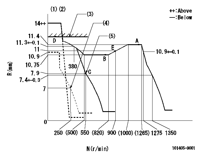
Test data Ex:
Governor adjustment

N:Pump speed
R:Rack position (mm)
(1)Target notch: K
(2)Tolerance for racks not indicated: +-0.05mm.
(3)RACK LIMIT
(4)Set idle sub-spring
(5)Main spring setting
----------
K=9
----------
----------
K=9
----------
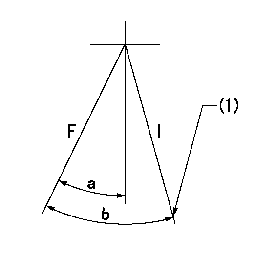
Speed control lever angle

F:Full speed
I:Idle
(1)Stopper bolt setting
----------
----------
a=16deg+-5deg b=22deg+-5deg
----------
----------
a=16deg+-5deg b=22deg+-5deg
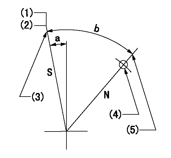
Stop lever angle

N:Pump normal
S:Stop the pump.
(1)Normal stop
(2)Rack position = aa, speed = bb.
(3)Stopper bolt setting
(4)Use the pin above R = cc
(5)Stopper bolt setting
----------
aa=1-0.5mm bb=0r/min cc=30mm
----------
a=13deg+-5deg b=(55deg)
----------
aa=1-0.5mm bb=0r/min cc=30mm
----------
a=13deg+-5deg b=(55deg)
Timing setting

(1)Pump vertical direction
(2)Position of camshaft's key groove at No 1 cylinder's beginning of injection
(3)-
(4)-
----------
----------
a=(60deg)
----------
----------
a=(60deg)
Information:
6. No or poor response to throttle
Active Diagnostic Codes: Troubleshoot any active diagnostic codes. ECM: Verify that ECM has completed its start-up self-checks and is out of cold mode. Throttle Position Signal: Check electrical connectors and wiring. Supply voltage to sensor should be between 22 and 27 V DC. Rack Controls: Check electrical connectors and wiring from ECM to rack position sensor and to rack BTM. Measure the signal output to the ECM. Also check for binding of servo or rack.7. Low power/Engine speed (rpm) restricted
Fuel Supply: Check for empty fuel tank, plugged fuel tank connections, obstructed or kinked fuel suction lines, plugged fuel filter, air in fuel system or kinked, leaking or broken fuel lines. Inlet Air System: Check for plugged air filter, aftercooler restrictions, aftercooler leaks, high inlet air temperature. Inspect all gaskets and piping for leaks. Exhaust System: Check for any restrictions. Fuel Injection Nozzle/Pump: If the engine is misfiring or engine speed (rpm) is restricted, run the engine at the speed where the problem is most pronounced. Momentarily loosen the fuel line nut on the injection pump to "cut out" that cylinder. Check each cylinder in this manner. If one is found where loosening makes no difference in irregular operation, the pump and nozzle for that cylinder should be inspected for damage, wear and proper operation. Inspect components for leaks and replace as needed. Fuel Injection Timing: See your authorized dealer. Valve Lash: Adjust valves to specified clearances. Turbocharger: Check for carbon buildup or restricted movement of turbo wheel. Replace if necessary. Auxiliary Attachments: Inspect, align, tighten and check for excessive parasitic loading. Active Diagnostic Codes: Troubleshoot any active diagnostic codes. Factory Parameters: Verify that Full Load Setting and Full Torque Setting are programmed to the values stamped on the engine information plate. Rack Controls: Check electrical connectors and wiring from ECM to rack position sensor and to rack BTM. Measure the signal output to the ECM. Also check for binding of servo or rack. Throttle Position Signal: Check electrical connectors and wiring. Supply voltage to sensor should be between 22 and 27 V DC.8. Intermittent engine shutdowns or power reduction
Fuel Supply: Check for empty fuel tank, plugged fuel tank connections, obstructed or kinked fuel suction lines, plugged fuel filter, air in fuel system or kinked, leaking or broken fuel lines. Shutoff Solenoid: Actuate the control that operates the shutoff solenoid and listen for a "clicking" sound. Power Supply to ECM: Check electrical connectors, wiring and voltage from battery to ECM. Power to ECM should measure 22 to 27 volts. Shutoff Solenoid: Check electrical connectors and wiring. Mechanically override the shutoff solenoid by attaching a lever to the fuel pump. Push lever backward to override the solenoid or forward to shutoff fuel supply. Rack Controls: Check electrical connectors and wiring from ECM to rack position sensor and to rack BTM. Measure the signal output to the ECM. Also check for binding of servo or rack. Engine Speed Signal: (Magnetic Pickup) Check electrical connectors and
Have questions with 101405-9001?
Group cross 101405-9001 ZEXEL
Yanmar
101405-9001
INJECTION-PUMP ASSEMBLY