Information injection-pump assembly
BOSCH
F 01G 0V0 004
f01g0v0004
ZEXEL
101405-3253
1014053253
Rating:
Include in #1:
101609-9223
as _
Cross reference number
BOSCH
F 01G 0V0 004
f01g0v0004
ZEXEL
101405-3253
1014053253
Zexel num
Bosch num
Firm num
Name
101405-3253
F 01G 0V0 004
6737711110 KOMATSU
INJECTION-PUMP ASSEMBLY
SAA4D102 K
SAA4D102 K
Calibration Data:
Adjustment conditions
Test oil
1404 Test oil ISO4113 or {SAEJ967d}
1404 Test oil ISO4113 or {SAEJ967d}
Test oil temperature
degC
40
40
45
Nozzle and nozzle holder
105780-8140
Bosch type code
EF8511/9A
Nozzle
105780-0000
Bosch type code
DN12SD12T
Nozzle holder
105780-2080
Bosch type code
EF8511/9
Opening pressure
MPa
17.2
Opening pressure
kgf/cm2
175
Injection pipe
Outer diameter - inner diameter - length (mm) mm 6-2-600
Outer diameter - inner diameter - length (mm) mm 6-2-600
Overflow valve
131424-3420
Overflow valve opening pressure
kPa
255
221
289
Overflow valve opening pressure
kgf/cm2
2.6
2.25
2.95
Tester oil delivery pressure
kPa
255
255
255
Tester oil delivery pressure
kgf/cm2
2.6
2.6
2.6
Direction of rotation (viewed from drive side)
Right R
Right R
Injection timing adjustment
Direction of rotation (viewed from drive side)
Right R
Right R
Injection order
1-3-4-2
Pre-stroke
mm
2.5
2.45
2.55
Beginning of injection position
Drive side NO.1
Drive side NO.1
Difference between angles 1
Cal 1-3 deg. 90 89.5 90.5
Cal 1-3 deg. 90 89.5 90.5
Difference between angles 2
Cal 1-4 deg. 180 179.5 180.5
Cal 1-4 deg. 180 179.5 180.5
Difference between angles 3
Cyl.1-2 deg. 270 269.5 270.5
Cyl.1-2 deg. 270 269.5 270.5
Injection quantity adjustment
Adjusting point
A
Rack position
9.8
Pump speed
r/min
1100
1100
1100
Average injection quantity
mm3/st.
103
102
104
Max. variation between cylinders
%
0
-2.5
2.5
Basic
*
Fixing the lever
*
Boost pressure
kPa
53.3
53.3
Boost pressure
mmHg
400
400
Hydraulic cylinder ON
*
Injection quantity adjustment_02
Adjusting point
-
Rack position
6.8+-0.5
Pump speed
r/min
420
420
420
Average injection quantity
mm3/st.
10
9
11
Max. variation between cylinders
%
0
-10
10
Fixing the rack
*
Boost pressure
kPa
0
0
0
Boost pressure
mmHg
0
0
0
Hydraulic cylinder ON
*
Remarks
Adjust only variation between cylinders; adjust governor according to governor specifications.
Adjust only variation between cylinders; adjust governor according to governor specifications.
Boost compensator adjustment
Pump speed
r/min
650
650
650
Rack position
8.4
Boost pressure
kPa
10
7.3
12.7
Boost pressure
mmHg
75
55
95
Boost compensator adjustment_02
Pump speed
r/min
650
650
650
Rack position
9.05
Boost pressure
kPa
18.7
16
21.4
Boost pressure
mmHg
140
120
160
Boost compensator adjustment_03
Pump speed
r/min
650
650
650
Rack position
10.35
Boost pressure
kPa
40
40
40
Boost pressure
mmHg
300
300
300
Test data Ex:
Governor adjustment
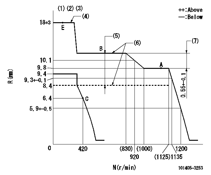
N:Pump speed
R:Rack position (mm)
(1)Target notch: K
(2)Tolerance for racks not indicated: +-0.05mm.
(3)Adjust the secondary timing before adjusting the governor.
(4)When the hydraulic cylinder is OFF
(5)Boost compensator stroke: BCL
(6)When hydraulic cylinder ON: P1
(7)Rack difference between N = N1 and N = N2
----------
K=12 BCL=(1.95)mm P1=(127+-10kPa{1.3+-0.1kgf/cm2}) N1=1100r/min N2=650r/min
----------
----------
K=12 BCL=(1.95)mm P1=(127+-10kPa{1.3+-0.1kgf/cm2}) N1=1100r/min N2=650r/min
----------
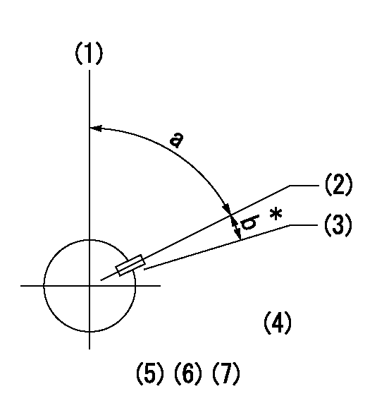
Speed control lever angle
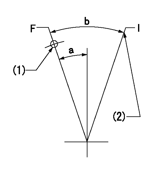
F:Full speed
I:Idle
(1)Use the hole at R = aa
(2)Stopper bolt setting
----------
aa=60mm
----------
a=18deg+-5deg b=35deg+-5deg
----------
aa=60mm
----------
a=18deg+-5deg b=35deg+-5deg
Stop lever angle
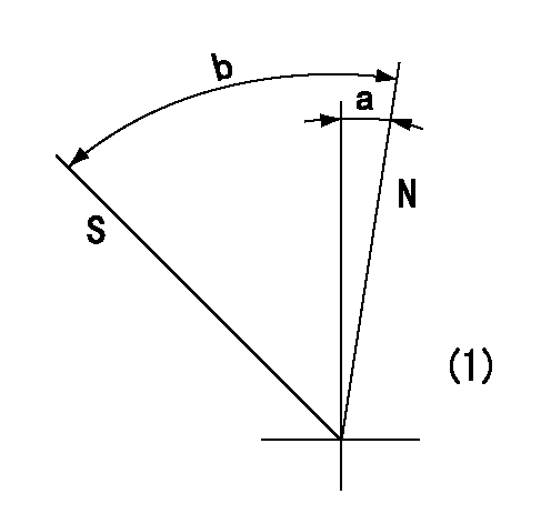
N:Pump normal
S:Stop the pump.
(1)No return spring
----------
----------
a=0deg+-5deg b=53deg+-5deg
----------
----------
a=0deg+-5deg b=53deg+-5deg
0000001501 TAMPER PROOF
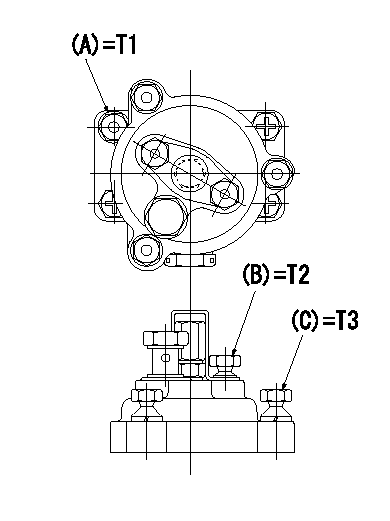
Tamperproofing-equipped boost compensator cover installation procedure
(1)After adjusting the governor and the boost compensator, tighten to the specified torque to break off the bolt heads.
(Tightening torque T = T1 maximum)
(2)After adjusting the governor and the boost compensator, tighten to the specified torque to break off the bolt heads.
(Tightening torque T = T2)
(3)After adjusting the governor and the boost compensator, tighten to the specified torque to break off the bolt heads.
(Tightening torque T = T3)
----------
T1=7.16~9.12N-m(0.73~0.93kgf-m) T2=2.9~4.4N-m(0.3~0.45kgf-m) T3=2.9~4.4N-m(0.3~0.45kgf-m)
----------
----------
T1=7.16~9.12N-m(0.73~0.93kgf-m) T2=2.9~4.4N-m(0.3~0.45kgf-m) T3=2.9~4.4N-m(0.3~0.45kgf-m)
----------
Timing setting
(1)Pump vertical direction
(2)Key groove position at No. 1 cylinder's beginning of injection position (at BTDC: aa).
(3)Position of the key groove of the No. 1 cylinder at B.T.D.C. bb (fix the governor flyweight at this position for delivery).
(4)B.T.D.C.: aa
(5)At second timing adjustment, set the camshaft at the * position and tighten the flyweight locknut.
(6)Align the flyweight's timing gear position with the lockpin groove and then fully tighten the flyweight to the camshaft.
(7)Remove the lock pin and adjust the governor. Reinstall the lock pin to fix the flyweight for delivery.
----------
aa=13deg bb=0deg
----------
a=54deg54min+-3deg b=6deg30min+-30min
----------
aa=13deg bb=0deg
----------
a=54deg54min+-3deg b=6deg30min+-30min
Information:
Engine and Attachment Lifting
When it is necessary to remove a component on an angle, remember that the capacity of an eyebolt is less as the angle between the supporting members and the object becomes less than 90 degrees. Eyebolts and brackets should never be bent and should only be loaded in tension.
Use a hoist to remove heavy components. Lift the engine by using an adjustable lifting beam. All supporting members (chains and cables) should be parallel to each other, and as near perpendicular as possible to the top of the object being lifted.To remove the engine ONLY, use the lifting eyes equipped with the engine. Lifting eyes are designed for the arrangement as sold and the end user is responsible for providing lifting devices. Alterations to lifting eyes and/or arrangement weight make the lifting eyes and devices obsolete. If you make alterations to the engine package as sold, you are responsible for providing adequate lifting devices.Engine Storage
These instructions and recommendations will safeguard the possibility of engine damage if the engines are in storage for one year or less.If the engine will not be or has not been started for several weeks, the lubricating oil will drain from the cylinder walls and piston rings.If an engine remains out of service and its use is not immediately planned, special precautions should be taken. Rust can form on the cylinder liner surface, which will increase engine wear and may result in shorter engine life. To prevent this problem from becoming excessive, be sure all lubrication recommendations mentioned in the Maintenance Schedule are completed.After one year, a complete protection procedure must be followed if the engine is kept in storage longer.If it will be impossible to start the engine periodically, consult your Caterpillar dealer for instructions to prepare your engine for longer storage periods.If an engine remains out of service and its use is not immediately planned, special precautions should be taken. Refer to Storage Procedures For Caterpillar Products, SEHS9031 for more detailed information on engine storage. To prevent excessive engine wear:Be sure all lubrication recommendations mentioned in the Maintenance Schedule intervals chart are completed.If freezing temperatures are expected, check the cooling system for adequate protection against freezing. A 50/50 solution of Caterpillar permanent-type antifreeze and approved water will give protection below -29°C (-20°F). The engine can be stored between temperatures -50°C (-58°F) and 85°C (185°F).
Have questions with 101405-3253?
Group cross 101405-3253 ZEXEL
Komatsu
Komatsu
101405-3253
F 01G 0V0 004
6737711110
INJECTION-PUMP ASSEMBLY
SAA4D102
SAA4D102