Information injection-pump assembly
ZEXEL
101405-3140
1014053140

Rating:
Cross reference number
ZEXEL
101405-3140
1014053140
Zexel num
Bosch num
Firm num
Name
101405-3140
INJECTION-PUMP ASSEMBLY
Calibration Data:
Adjustment conditions
Test oil
1404 Test oil ISO4113 or {SAEJ967d}
1404 Test oil ISO4113 or {SAEJ967d}
Test oil temperature
degC
40
40
45
Nozzle and nozzle holder
105780-8140
Bosch type code
EF8511/9A
Nozzle
105780-0000
Bosch type code
DN12SD12T
Nozzle holder
105780-2080
Bosch type code
EF8511/9
Opening pressure
MPa
17.2
Opening pressure
kgf/cm2
175
Injection pipe
Outer diameter - inner diameter - length (mm) mm 6-2-600
Outer diameter - inner diameter - length (mm) mm 6-2-600
Overflow valve
131424-3420
Overflow valve opening pressure
kPa
255
221
289
Overflow valve opening pressure
kgf/cm2
2.6
2.25
2.95
Tester oil delivery pressure
kPa
157
157
157
Tester oil delivery pressure
kgf/cm2
1.6
1.6
1.6
Direction of rotation (viewed from drive side)
Right R
Right R
Injection timing adjustment
Direction of rotation (viewed from drive side)
Right R
Right R
Injection order
1-3-4-2
Pre-stroke
mm
2.5
2.45
2.55
Beginning of injection position
Drive side NO.1
Drive side NO.1
Difference between angles 1
Cal 1-3 deg. 90 89.5 90.5
Cal 1-3 deg. 90 89.5 90.5
Difference between angles 2
Cal 1-4 deg. 180 179.5 180.5
Cal 1-4 deg. 180 179.5 180.5
Difference between angles 3
Cyl.1-2 deg. 270 269.5 270.5
Cyl.1-2 deg. 270 269.5 270.5
Injection quantity adjustment
Adjusting point
A
Rack position
9.7
Pump speed
r/min
1100
1100
1100
Average injection quantity
mm3/st.
93.5
92.5
94.5
Max. variation between cylinders
%
0
-2.5
2.5
Basic
*
Fixing the lever
*
Injection quantity adjustment_02
Adjusting point
-
Rack position
7+-0.5
Pump speed
r/min
465
465
465
Average injection quantity
mm3/st.
11.5
10.5
12.5
Max. variation between cylinders
%
0
-15
15
Fixing the rack
*
Remarks
Adjust only variation between cylinders; adjust governor according to governor specifications.
Adjust only variation between cylinders; adjust governor according to governor specifications.
Injection quantity adjustment_03
Adjusting point
D
Rack position
-
Pump speed
r/min
100
100
100
Average injection quantity
mm3/st.
85
85
95
Fixing the lever
*
Rack limit
*
Test data Ex:
Governor adjustment
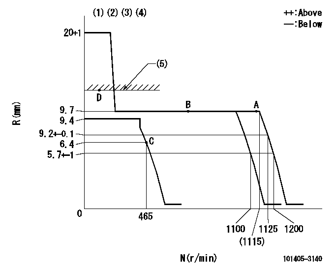
N:Pump speed
R:Rack position (mm)
(1)Target notch: K
(2)Tolerance for racks not indicated: +-0.05mm.
(3)The torque control spring does not operate.
(4)Adjust the secondary timing before adjusting the governor.
(5)RACK LIMIT
----------
K=15
----------
----------
K=15
----------
Speed control lever angle
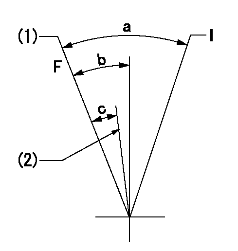
F:Full speed
I:Idle
(1)Speed = aa (active mode)
(2)Speed = bb (normal mode)
----------
aa=1125r/min bb=1100r/min
----------
a=35deg+-5deg b=18deg+-5deg c=5deg+-5deg
----------
aa=1125r/min bb=1100r/min
----------
a=35deg+-5deg b=18deg+-5deg c=5deg+-5deg
Stop lever angle
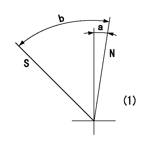
N:Pump normal
S:Stop the pump.
(1)No return spring
----------
----------
a=0deg+-5deg b=53deg+-5deg
----------
----------
a=0deg+-5deg b=53deg+-5deg
Timing setting
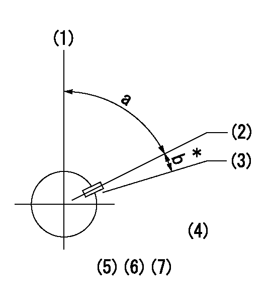
(1)Pump vertical direction
(2)Key groove position at No. 1 cylinder's beginning of injection position (at BTDC: aa).
(3)Position of the key groove of the No. 1 cylinder at B.T.D.C. bb (fix the governor flyweight at this position for delivery).
(4)B.T.D.C.: aa
(5)At second timing adjustment, set the camshaft at the * position and tighten the flyweight locknut.
(6)Align the flyweight's timing gear position with the lockpin groove and then fully tighten the flyweight to the camshaft.
(7)Remove the lock pin and adjust the governor. Reinstall the lock pin to fix the flyweight for delivery.
----------
aa=16deg bb=0deg
----------
a=54deg54min+-3deg b=8deg+-30min
----------
aa=16deg bb=0deg
----------
a=54deg54min+-3deg b=8deg+-30min
Information:
* Inspect the radiator for leaks and trash build-up. * Inspect the radiator hoses for cracks and loose clamps. * Inspect the fan and accessory drive belts for cracks, breaks or other damage.Belts for multiple groove pulleys must be replaced as matched sets. If only one belt of a 2 or 3 belt set is replaced, it will carry more of a load than the belts not replaced since the older belts are stretched. The additional load on the new belt could cause it to break. * Inspect the water pump for leaks. * Inspect the engine for oil leaks, such as front and rear crankshaft seals, oil pan, oil filters and valve covers. * Inspect the fuel system for leaks, loose fuel line clamps and fittings and loose or worn hoses. * Inspect wiring for loose connections and worn or frayed wires. * Inspect air intake system hoses and elbows for cracks and loose clamps. * Inspect ECM to cylinder head ground strap for good connection and condition.* Inspect engine-to-frame ground strap for good connection and condition.* All guards must be in place. Repair or replace missing or damaged guards.Engine Crankcase
Check Oil Level
Make sure you read and understand the information in the Lubricant Specifications section of this manual before you proceed with maintenance of the crankcase lube oil system.
The vehicle must be parked on a level surface to perform this maintenance procedure.
1. Check the oil level with the engine stopped. 2. Maintain the oil level between the ADD and FULL marks in the FULL RANGE zone on the ENGINE STOPPED side of the dipstick. Do not fill the crankcase above the FULL RANGE zone. Operating your engine when the oil level is above the FULL RANGE zone could cause your crankshaft to dip into the oil. If this happens, the air bubbles created from the crankshaft dipping into the oil will reduce the lubricating characteristics of your oil and would result in the loss of power.If the dipstick does not have a FULL mark in the FULL RANGE zone, refer to Calibrating the oil level gauge in the Dipstick section of this manual or consult your Caterpillar dealer before changing oil and operating the engine. 3. Remove the oil filler cap and add oil if necessary. See Refill Capacities and Lubricant Specifications for the size of your engine crankcase and proper oil to use. Remote mounted or auxiliary filters require additional oil. For all information pertaining to auxiliary filters, refer to the OEM or filter manufacturer's instructions.Cooling System
Check Coolant Level
Make sure you read and understand the information in the "Cooling System Specifications" section of this manual before you proceed with maintenance of the cooling system.
1. Check the coolant level with the engine stopped and cool.2. Remove the filler cap slowly to relieve any pressure.3. Maintain the coolant level within 13 mm (1/2 inch) below the bottom of the fill pipe or to the proper level on the sight glass, if equipped. 4. Inspect the filler cap.Replace the
Have questions with 101405-3140?
Group cross 101405-3140 ZEXEL
Komatsu
101405-3140
INJECTION-PUMP ASSEMBLY