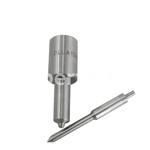
Information injection-pump assembly
BOSCH
9 400 611 233
9400611233
ZEXEL
101403-9130
1014039130
Rating:
Service parts 101403-9130 INJECTION-PUMP ASSEMBLY:
1.
_
6.
COUPLING PLATE
7.
COUPLING PLATE
8.
_
9.
_
11.
Nozzle and Holder
12.
Open Pre:MPa(Kqf/cm2)
18.1{185}
15.
NOZZLE SET
Cross reference number
BOSCH
9 400 611 233
9400611233
ZEXEL
101403-9130
1014039130
Zexel num
Bosch num
Firm num
Name
101403-9130
9 400 611 233
CHINA
INJECTION-PUMP ASSEMBLY
4102BZ K 14BD INJECTION PUMP ASSY PE4AD PE
4102BZ K 14BD INJECTION PUMP ASSY PE4AD PE
Calibration Data:
Adjustment conditions
Test oil
1404 Test oil ISO4113 or {SAEJ967d}
1404 Test oil ISO4113 or {SAEJ967d}
Test oil temperature
degC
40
40
45
Nozzle and nozzle holder
105780-8140
Bosch type code
EF8511/9A
Nozzle
105780-0000
Bosch type code
DN12SD12T
Nozzle holder
105780-2080
Bosch type code
EF8511/9
Opening pressure
MPa
17.2
Opening pressure
kgf/cm2
175
Injection pipe
Outer diameter - inner diameter - length (mm) mm 6-2-600
Outer diameter - inner diameter - length (mm) mm 6-2-600
Overflow valve
131424-1520
Overflow valve opening pressure
kPa
157
123
191
Overflow valve opening pressure
kgf/cm2
1.6
1.25
1.95
Tester oil delivery pressure
kPa
157
157
157
Tester oil delivery pressure
kgf/cm2
1.6
1.6
1.6
Direction of rotation (viewed from drive side)
Right R
Right R
Injection timing adjustment
Direction of rotation (viewed from drive side)
Right R
Right R
Injection order
1-3-4-2
Pre-stroke
mm
3.8
3.75
3.85
Beginning of injection position
Drive side NO.1
Drive side NO.1
Difference between angles 1
Cal 1-3 deg. 90 89.5 90.5
Cal 1-3 deg. 90 89.5 90.5
Difference between angles 2
Cal 1-4 deg. 180 179.5 180.5
Cal 1-4 deg. 180 179.5 180.5
Difference between angles 3
Cyl.1-2 deg. 270 269.5 270.5
Cyl.1-2 deg. 270 269.5 270.5
Injection quantity adjustment
Adjusting point
-
Rack position
12.5
Pump speed
r/min
800
800
800
Average injection quantity
mm3/st.
80.5
78.9
82.1
Max. variation between cylinders
%
0
-2.5
2.5
Basic
*
Fixing the rack
*
Standard for adjustment of the maximum variation between cylinders
*
Injection quantity adjustment_02
Adjusting point
H
Rack position
9.5+-0.5
Pump speed
r/min
350
350
350
Average injection quantity
mm3/st.
8
6.7
9.3
Max. variation between cylinders
%
0
-10
10
Fixing the rack
*
Standard for adjustment of the maximum variation between cylinders
*
Injection quantity adjustment_03
Adjusting point
A
Rack position
R1(12.5)
Pump speed
r/min
800
800
800
Average injection quantity
mm3/st.
80.5
79.5
81.5
Basic
*
Fixing the lever
*
Boost pressure
kPa
30.7
30.7
Boost pressure
mmHg
230
230
Injection quantity adjustment_04
Adjusting point
I
Rack position
-
Pump speed
r/min
100
100
100
Average injection quantity
mm3/st.
110
110
130
Fixing the lever
*
Boost pressure
kPa
0
0
0
Boost pressure
mmHg
0
0
0
Rack limit
*
Boost compensator adjustment
Pump speed
r/min
400
400
400
Rack position
R2-1
Boost pressure
kPa
10
8.7
11.3
Boost pressure
mmHg
75
65
85
Boost compensator adjustment_02
Pump speed
r/min
400
400
400
Rack position
R2(R1-1.
1)
Boost pressure
kPa
17.3
17.3
17.3
Boost pressure
mmHg
130
130
130
Timer adjustment
Pump speed
r/min
1050--
Advance angle
deg.
0
0
0
Remarks
Start
Start
Timer adjustment_02
Pump speed
r/min
1000
Advance angle
deg.
0.5
Timer adjustment_03
Pump speed
r/min
1400
Advance angle
deg.
4
3.5
4.5
Remarks
Finish
Finish
Test data Ex:
Governor adjustment
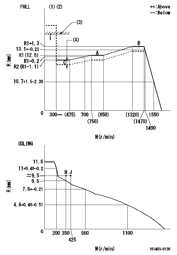
N:Pump speed
R:Rack position (mm)
(1)Torque cam stamping: T1
(2)Tolerance for racks not indicated: +-0.05mm.
(3)RACK LIMIT
(4)Boost compensator stroke: BCL
----------
T1=P04 BCL=1+-0.1mm
----------
----------
T1=P04 BCL=1+-0.1mm
----------
Speed control lever angle
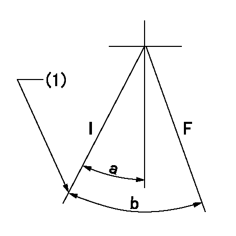
F:Full speed
I:Idle
(1)Stopper bolt set position 'H'
----------
----------
a=23.5deg+-5deg b=42deg+-3deg
----------
----------
a=23.5deg+-5deg b=42deg+-3deg
Stop lever angle
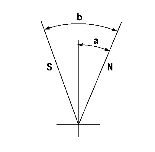
N:Pump normal
S:Stop the pump.
----------
----------
a=25deg+-5deg b=40deg+-5deg
----------
----------
a=25deg+-5deg b=40deg+-5deg
Timing setting

(1)Pump vertical direction
(2)Position of gear mark 'CC' at No 1 cylinder's beginning of injection
(3)B.T.D.C.: aa
(4)-
----------
aa=15deg
----------
a=(100deg)
----------
aa=15deg
----------
a=(100deg)
Information:
You must read and understand the warnings and instructions contained in the Safety section of this manual before performing any operation or maintenance procedures.This maintenance is to be performed at the interval specified in the Maintenance Schedule for the engine being maintained.Before proceeding with 125 Service Hour maintenance, first perform previous maintenance requirements.Clutch (If Equipped)
Refer to the Instruction Plate on your clutch for the correct lubrication information.Lubricate Shift Collar Bearings
Instruction PlateLubricate the shift collar fittings with one or two grease gun shots each with MPGL or 2S3230 grease. Do not over grease.Lubricate Shift Lever Bearings
Refer to the Instruction Plate on the clutch for lubrication information.Some earlier clutches have pilot bearing fittings that need lubrication, whereas the later clutches have pilot bearings that are sealed for life.Lubricate the clutch shift lever bearings, pilot bearing and main shaft bearing (if equipped). Lubricate one fitting on top-rear of housing. Lubricate one fitting at the end of shaft. Refer to Instruction Plate on your clutch for correct lubrication information.Check/Adjust
If the clutch is damaged to the point of burst failure, expelled pieces can cause personal injury to anyone in the immediate area. Proper safeguards must be followed to prevent accidents.Do NOT operate the engine with Instruction Plate cover removed from the clutch. Personal injury may result.
While engaging the clutch to pick up the load, check the clutch adjustment. The clutch should engage with a firm push of the lever and a distinct snap. If the engagement is "soft" or slow, adjust the clutch.When clutch lever is disengaged, the hand lever must fall behind the vertical position. If the clutch slips, overheats, or operating lever disengages, clutch adjustment is necessary.1. Stop the engine and remove the clutch inspection cover.2. Rotate the clutch manually until the lock pin (engaged in the locking ring) is visible.3. Pull the lock pin out and rotate the locking ring clockwise (CW) until the lock pin slips or pops into the next notch. Turn adjusting ring CW to increase engagement torque and CCW to decrease engagement torque.4. Test the clutch adjustment. To test the clutch adjustment, engage clutch with a torque wrench to turn adjusting ring so that 296 to 393 N m (218 to 289 lb ft)torque or 636 90 N (143 20 lb) force at 541 mm (21.3 inches) length on lever is required to engage the clutch. If torque is still low, rotate the locking ring (CW) until lock pin slips into next notch. If the adjustment is too tight, turn the locking ring back (CCW) one to the previous notch.5. Install cover plate after adjustment is completed.
Have questions with 101403-9130?
Group cross 101403-9130 ZEXEL
Dpico
China
101403-9130
9 400 611 233
INJECTION-PUMP ASSEMBLY
4102BZ
4102BZ
