Information injection-pump assembly
BOSCH
9 400 611 880
9400611880
ZEXEL
101402-9980
1014029980

Rating:
Service parts 101402-9980 INJECTION-PUMP ASSEMBLY:
1.
_
5.
AUTOM. ADVANCE MECHANIS
6.
COUPLING PLATE
7.
COUPLING PLATE
8.
_
9.
_
10.
NOZZLE AND HOLDER ASSY
11.
Nozzle and Holder
12.
Open Pre:MPa(Kqf/cm2)
13.
NOZZLE-HOLDER
14.
NOZZLE
15.
NOZZLE SET
Cross reference number
BOSCH
9 400 611 880
9400611880
ZEXEL
101402-9980
1014029980
Zexel num
Bosch num
Firm num
Name
Calibration Data:
Adjustment conditions
Test oil
1404 Test oil ISO4113 or {SAEJ967d}
1404 Test oil ISO4113 or {SAEJ967d}
Test oil temperature
degC
40
40
45
Nozzle and nozzle holder
105780-8140
Bosch type code
EF8511/9A
Nozzle
105780-0000
Bosch type code
DN12SD12T
Nozzle holder
105780-2080
Bosch type code
EF8511/9
Opening pressure
MPa
17.2
Opening pressure
kgf/cm2
175
Injection pipe
Outer diameter - inner diameter - length (mm) mm 6-2-600
Outer diameter - inner diameter - length (mm) mm 6-2-600
Overflow valve
131424-1520
Overflow valve opening pressure
kPa
157
123
191
Overflow valve opening pressure
kgf/cm2
1.6
1.25
1.95
Tester oil delivery pressure
kPa
157
157
157
Tester oil delivery pressure
kgf/cm2
1.6
1.6
1.6
Direction of rotation (viewed from drive side)
Right R
Right R
Injection timing adjustment
Direction of rotation (viewed from drive side)
Right R
Right R
Injection order
1-3-4-2
Pre-stroke
mm
3.3
3.25
3.35
Beginning of injection position
Drive side NO.1
Drive side NO.1
Difference between angles 1
Cal 1-3 deg. 90 89.5 90.5
Cal 1-3 deg. 90 89.5 90.5
Difference between angles 2
Cal 1-4 deg. 180 179.5 180.5
Cal 1-4 deg. 180 179.5 180.5
Difference between angles 3
Cyl.1-2 deg. 270 269.5 270.5
Cyl.1-2 deg. 270 269.5 270.5
Injection quantity adjustment
Adjusting point
A
Rack position
10.4
Pump speed
r/min
900
900
900
Average injection quantity
mm3/st.
76
75
77
Max. variation between cylinders
%
0
-2.5
2.5
Basic
*
Fixing the lever
*
Injection quantity adjustment_02
Adjusting point
C
Rack position
7.2+-0.5
Pump speed
r/min
600
600
600
Average injection quantity
mm3/st.
12
11
13
Max. variation between cylinders
%
0
-15
15
Fixing the rack
*
Injection quantity adjustment_03
Adjusting point
D
Rack position
10.6++
Pump speed
r/min
100
100
100
Average injection quantity
mm3/st.
100
95
105
Fixing the lever
*
Rack limit
*
Test data Ex:
Governor adjustment
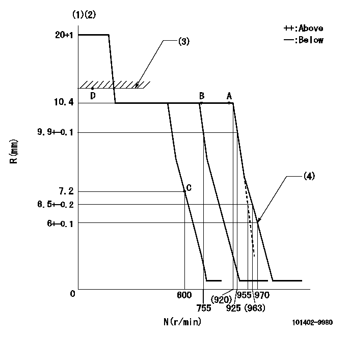
N:Pump speed
R:Rack position (mm)
(1)Target notch: K
(2)Tolerance for racks not indicated: +-0.05mm.
(3)RACK LIMIT
(4)Set idle sub-spring
----------
K=7
----------
----------
K=7
----------
Speed control lever angle
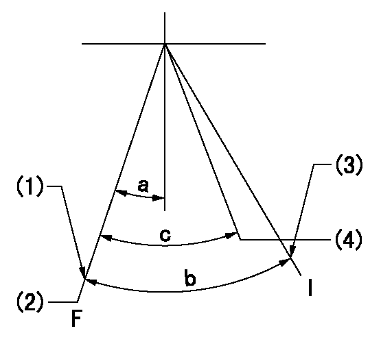
F:Full speed
I:Idle
(1)Stopper bolt setting
(2)Set the pump speed at aa
(3)Stopper bolt setting
(4)When pump speed set at bb
----------
aa=925r/min bb=755r/min
----------
a=4deg+-5deg b=14deg+-5deg c=7deg+-5deg
----------
aa=925r/min bb=755r/min
----------
a=4deg+-5deg b=14deg+-5deg c=7deg+-5deg
Stop lever angle
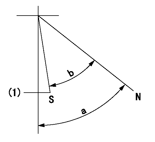
N:Pump normal
S:Stop the pump.
(1)Normal stop
----------
----------
a=58deg+-5deg b=53deg+-5deg
----------
----------
a=58deg+-5deg b=53deg+-5deg
Timing setting

(1)Pump vertical direction
(2)Position of camshaft's key groove at No 1 cylinder's beginning of injection
(3)-
(4)-
----------
----------
a=(60deg)
----------
----------
a=(60deg)
Information:
The combustion process of a diesel engine produces exhaust products such as smoke (visible), hydrocarbons and oxides of nitrogen (invisible). The dark smoke emitted by a diesel engine is soot or carbon particles and even in low concentration make the diesel exhaust highly visible and offensive to most people. Every effort must be made to eliminate smoke even though it can be considered more of a nuisance than a pollutant.Under certain conditions oxides of nitrogen react with certain hydrocarbons to form smog which can become irritating and toxic if large concentrations accumulate. Concentrations of this pollutant combined with pollution of other sources all contribute to the total air quality problem.As an engine manufacturer, our goal is to see that environmental standards are met with a minimum additional complexity or cost to the product. Throughout the years, continuing research and design improvements have been directed at minimizing exhaust emissions. Caterpillar has incorporated items such as -TURBOCHARGING: Reduces exhaust noise and provides more air per cylinder allowing the fuel to burn more efficiently. These engines are integrally designed for turbocharging.AIR-FUEL RATIO CONTROL FOR TURBOCHARGED ENGINES: Limits the amount of fuel during acceleration to minimize smoke levels.RECOMMEND FUELS, LUBRICATING OILS AND MAINTENANCE SCHEDULES: To assure minimum exhaust emissions.Maintenance Recommendations
Caterpillar Truck Engines are certified by the United States Environmental Protection Agency to comply with smoke emission standard limits prescribed by Federal laws at the time of manufacture.Efficiency of emission control and good engine performance depend on adherence to proper operation and maintenance recommendations, use of recommended fuels and lubricating oils. It is recommended that major adjustments and repair be entrusted to your authorized dealer.Various chemical fuel additives are commercially available that claim to reduce visible smoke. Although additives have been used by individuals to solve some isolated smoke problems in the field, they are not recommended for general use. Federal smoke regulations require the certification of engines without a smoke depressant.The corrective steps taken immediately on discovery of worn parts, which may affect emission levels, will help assure proper operation of emission control systems. The use of genuine Caterpillar parts is recommended. Suppliers of non-Caterpillar parts must assure the user that the use of such parts will not adversely affect emission levels.Regular service intervals along with special emphasis on the following items are necessary to keep exhaust emissions within acceptable limits for the useful life of the engine. Refer to the Lubrication and Maintenance Section of this Operation Guide for details and maintenance schedule. If the engine is operating under severe conditions, adjust maintenance schedule accordingly. See your authorized dealer to help analyze your specific maintenance schedule.The following explanation of required emission related component maintenance has been keyed by number to correspond with item number in the maintenance chart.1. COOLANT - LEVEL AND PROTECTION: Check the engine coolant level daily with the engine stopped and cool. Release cooling system pressure before checking. Fill to proper level with permanent-type antifreeze and water as free as possible from scale forming minerals. DO NOT USE
Caterpillar Truck Engines are certified by the United States Environmental Protection Agency to comply with smoke emission standard limits prescribed by Federal laws at the time of manufacture.Efficiency of emission control and good engine performance depend on adherence to proper operation and maintenance recommendations, use of recommended fuels and lubricating oils. It is recommended that major adjustments and repair be entrusted to your authorized dealer.Various chemical fuel additives are commercially available that claim to reduce visible smoke. Although additives have been used by individuals to solve some isolated smoke problems in the field, they are not recommended for general use. Federal smoke regulations require the certification of engines without a smoke depressant.The corrective steps taken immediately on discovery of worn parts, which may affect emission levels, will help assure proper operation of emission control systems. The use of genuine Caterpillar parts is recommended. Suppliers of non-Caterpillar parts must assure the user that the use of such parts will not adversely affect emission levels.Regular service intervals along with special emphasis on the following items are necessary to keep exhaust emissions within acceptable limits for the useful life of the engine. Refer to the Lubrication and Maintenance Section of this Operation Guide for details and maintenance schedule. If the engine is operating under severe conditions, adjust maintenance schedule accordingly. See your authorized dealer to help analyze your specific maintenance schedule.The following explanation of required emission related component maintenance has been keyed by number to correspond with item number in the maintenance chart.1. COOLANT - LEVEL AND PROTECTION: Check the engine coolant level daily with the engine stopped and cool. Release cooling system pressure before checking. Fill to proper level with permanent-type antifreeze and water as free as possible from scale forming minerals. DO NOT USE