Information injection-pump assembly
BOSCH
9 400 612 937
9400612937
ZEXEL
101402-9971
1014029971
YANMAR
12390051000
12390051000
Rating:
Service parts 101402-9971 INJECTION-PUMP ASSEMBLY:
1.
_

5.
AUTOM. ADVANCE MECHANIS
6.
COUPLING PLATE
7.
COUPLING PLATE
8.
_
9.
_
10.
NOZZLE AND HOLDER ASSY
11.
Nozzle and Holder
12.
Open Pre:MPa(Kqf/cm2)
13.
NOZZLE-HOLDER
14.
NOZZLE
15.
NOZZLE SET
Cross reference number
BOSCH
9 400 612 937
9400612937
ZEXEL
101402-9971
1014029971
YANMAR
12390051000
12390051000
Zexel num
Bosch num
Firm num
Name
101402-9971
9 400 612 937
12390051000 YANMAR
INJECTION-PUMP ASSEMBLY
4TNE106 K 14BC INJECTION PUMP ASSY PE4A,5A, PE
4TNE106 K 14BC INJECTION PUMP ASSY PE4A,5A, PE
Calibration Data:
Adjustment conditions
Test oil
1404 Test oil ISO4113 or {SAEJ967d}
1404 Test oil ISO4113 or {SAEJ967d}
Test oil temperature
degC
40
40
45
Nozzle and nozzle holder
105780-8140
Bosch type code
EF8511/9A
Nozzle
105780-0000
Bosch type code
DN12SD12T
Nozzle holder
105780-2080
Bosch type code
EF8511/9
Opening pressure
MPa
17.2
Opening pressure
kgf/cm2
175
Injection pipe
Outer diameter - inner diameter - length (mm) mm 6-2-600
Outer diameter - inner diameter - length (mm) mm 6-2-600
Overflow valve
131424-1520
Overflow valve opening pressure
kPa
157
123
191
Overflow valve opening pressure
kgf/cm2
1.6
1.25
1.95
Tester oil delivery pressure
kPa
157
157
157
Tester oil delivery pressure
kgf/cm2
1.6
1.6
1.6
Direction of rotation (viewed from drive side)
Right R
Right R
Injection timing adjustment
Direction of rotation (viewed from drive side)
Right R
Right R
Injection order
1-3-4-2
Pre-stroke
mm
3.3
3.25
3.35
Beginning of injection position
Drive side NO.1
Drive side NO.1
Difference between angles 1
Cal 1-3 deg. 90 89.5 90.5
Cal 1-3 deg. 90 89.5 90.5
Difference between angles 2
Cal 1-4 deg. 180 179.5 180.5
Cal 1-4 deg. 180 179.5 180.5
Difference between angles 3
Cyl.1-2 deg. 270 269.5 270.5
Cyl.1-2 deg. 270 269.5 270.5
Injection quantity adjustment
Adjusting point
A
Rack position
10.7
Pump speed
r/min
1250
1250
1250
Average injection quantity
mm3/st.
73.5
72.5
74.5
Max. variation between cylinders
%
0
-2.5
2.5
Basic
*
Fixing the lever
*
Injection quantity adjustment_02
Adjusting point
C
Rack position
7.6+-0.5
Pump speed
r/min
550
550
550
Average injection quantity
mm3/st.
13
12
14
Max. variation between cylinders
%
0
-15
15
Fixing the rack
*
Injection quantity adjustment_03
Adjusting point
D
Rack position
11.6++
Pump speed
r/min
100
100
100
Average injection quantity
mm3/st.
100
95
105
Fixing the lever
*
Rack limit
*
Test data Ex:
Governor adjustment
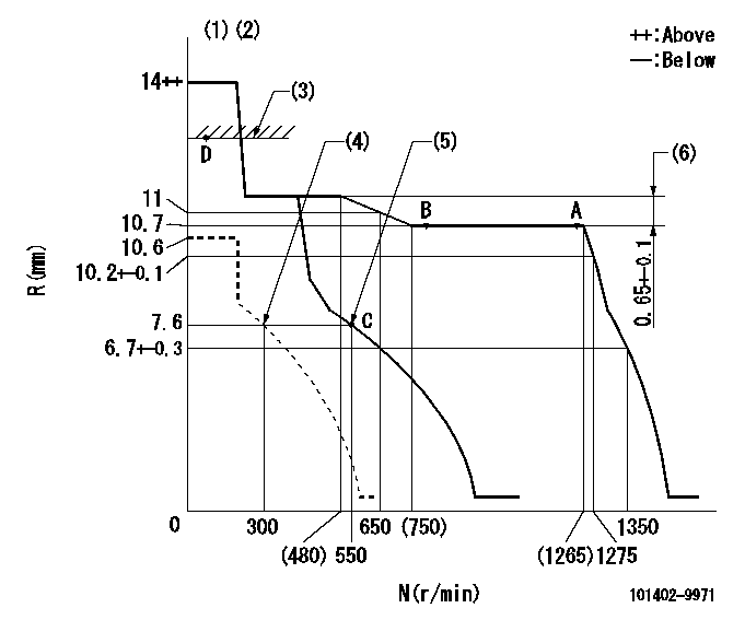
N:Pump speed
R:Rack position (mm)
(1)Target notch: K
(2)Tolerance for racks not indicated: +-0.05mm.
(3)RACK LIMIT
(4)Set idle sub-spring
(5)Main spring setting
(6)Rack difference between N = N1 and N = N2
----------
K=12 N1=1250r/min N2=400r/min
----------
----------
K=12 N1=1250r/min N2=400r/min
----------
Speed control lever angle

F:Full speed
I:Idle
(1)Stopper bolt setting
----------
----------
a=17deg+-5deg b=26deg+-5deg
----------
----------
a=17deg+-5deg b=26deg+-5deg
Stop lever angle
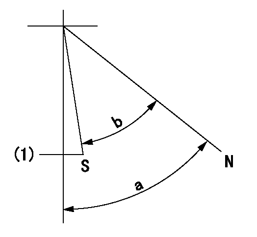
N:Pump normal
S:Stop the pump.
(1)Normal stop
----------
----------
a=58deg+-5deg b=53deg+-5deg
----------
----------
a=58deg+-5deg b=53deg+-5deg
Timing setting

(1)Pump vertical direction
(2)Position of camshaft's key groove at No 1 cylinder's beginning of injection
(3)-
(4)-
----------
----------
a=(60deg)
----------
----------
a=(60deg)
Information:
Tachometer Drive
Use a short fiber grease, No. 2 Grade for most temperatures, or No. 0 or No. 1 for extremely low temperatures. Wipe surrounding area with a clean rag before removing plug. Remove plug. Install grease fitting. Apply two strokes of lubricant through the fitting. Remove grease fitting. Replace plug.Governor Control Cross Shaft Bearings (1673)
Engines Before 69D3625)
Use a short fiber grease No. 2 Grade for most temperatures, or No. 0 or No. 1 for extremely low temperatures. Apply 1 stroke of lubricant through fitting at each end of shaft.Valve Adjustment
1673C
Make valve adjustment with engine stopped and cold. Remove the flywheel timing cover and rotate flywheel in direction of engine rotation until "TC 1-6 cyl" mark aligns with timing pointer. Remove valve cover and observe position of valves to determine if No. 1 or No. 6 piston is on compression stroke. Both the inlet and exhaust valves will be closed on compression stroke.1. With No. 1 piston at TDC on compression, check lash on exhaust valves for cylinders 1, 3 and 5, and inlet valves for cylinders 1, 2 and 4.2. To adjust, loosen valve adjusting locknut and turn adjusting screw to allow feeler gauge to pass between top of valve stem and the valve rocker arm.3. Set lash at .015" (0.38 mm) for inlet and .025" (0.63 mm) for exhaust valves.4. Tighten adjusting screw locknut and check lash clearance.5. Turn flywheel 360° in direction of engine rotation. Align flywheel timing mark with pointer. No. 6 cylinder will be at TDC compression stroke (valves closed).6. Check lash on exhaust valves for cylinders 2, 4 and 6, and inlet valves for cylinders 3, 5 and 6. Adjust valves if necessary.1674
Make valve lash adjustment with engine stopped. TDC of the No. 1 piston on the compression stroke is the reference point. The No. 1 piston will be at TDC when the No. 1 and No. 6 flywheel timing mark aligns with the timing pointer. Compression stroke is when all the No. 1 piston valves are closed.1. With No. 1 piston at TDC compression stroke, adjust lash on 1, 3 and 5 exhaust and 1, 2 and 4 inlet valves.2. Turn adjusting screw counterclockwise 2 clicks or more to provide clearance between rocker assembly and valve.3. Turn adjusting screw clockwise to obtain zero lash. There should be no free rocker movement or adjusting screw button lateral movement. The adjusting screw button can still be rotated by finger pressure even when it is in contact with valve stem and clearance is zero. Turning the adjusting screw clockwise beyond this point will force the valve off its seat, and final lash setting will be incorrect.4. To adjust, turn adjustment screw counterclockwise 10 clicks (.020") (0.51 mm) for the exhaust valves and 4 clicks (.008") (0.20 mm) for the inlet valves. (One click is equal to .002") (0.05 mm).5. Turn crankshaft 360° clockwise, (direction of normal rotation) viewing from front. Align flywheel timing mark with timing pointer. a) Adjust 2, 4 and 6 exhaust
Have questions with 101402-9971?
Group cross 101402-9971 ZEXEL
Daewoo
Daewoo
Yanmar
Mitsubishi-Heav
Yanmar
Yanmar
Yanmar
Yanmar
101402-9971
9 400 612 937
12390051000
INJECTION-PUMP ASSEMBLY
4TNE106
4TNE106