Information injection-pump assembly
BOSCH
9 400 611 229
9400611229
ZEXEL
101402-9961
1014029961
YANMAR
12398251000
12398251000
Rating:
Service parts 101402-9961 INJECTION-PUMP ASSEMBLY:
1.
_

5.
AUTOM. ADVANCE MECHANIS
6.
COUPLING PLATE
7.
COUPLING PLATE
8.
_
9.
_
10.
NOZZLE AND HOLDER ASSY
11.
Nozzle and Holder
12.
Open Pre:MPa(Kqf/cm2)
21.6{220}
13.
NOZZLE-HOLDER
14.
NOZZLE
15.
NOZZLE SET
Cross reference number
BOSCH
9 400 611 229
9400611229
ZEXEL
101402-9961
1014029961
YANMAR
12398251000
12398251000
Zexel num
Bosch num
Firm num
Name
9 400 611 229
12398251000 YANMAR
INJECTION-PUMP ASSEMBLY
4TNE106 K 14BC INJECTION PUMP ASSY PE4A,5A, PE
4TNE106 K 14BC INJECTION PUMP ASSY PE4A,5A, PE
Calibration Data:
Adjustment conditions
Test oil
1404 Test oil ISO4113 or {SAEJ967d}
1404 Test oil ISO4113 or {SAEJ967d}
Test oil temperature
degC
40
40
45
Nozzle and nozzle holder
105780-8140
Bosch type code
EF8511/9A
Nozzle
105780-0000
Bosch type code
DN12SD12T
Nozzle holder
105780-2080
Bosch type code
EF8511/9
Opening pressure
MPa
17.2
Opening pressure
kgf/cm2
175
Injection pipe
Outer diameter - inner diameter - length (mm) mm 6-2-600
Outer diameter - inner diameter - length (mm) mm 6-2-600
Overflow valve
131424-1520
Overflow valve opening pressure
kPa
157
123
191
Overflow valve opening pressure
kgf/cm2
1.6
1.25
1.95
Tester oil delivery pressure
kPa
157
157
157
Tester oil delivery pressure
kgf/cm2
1.6
1.6
1.6
Direction of rotation (viewed from drive side)
Right R
Right R
Injection timing adjustment
Direction of rotation (viewed from drive side)
Right R
Right R
Injection order
1-3-4-2
Pre-stroke
mm
3.3
3.25
3.35
Beginning of injection position
Drive side NO.1
Drive side NO.1
Difference between angles 1
Cal 1-3 deg. 90 89.5 90.5
Cal 1-3 deg. 90 89.5 90.5
Difference between angles 2
Cal 1-4 deg. 180 179.5 180.5
Cal 1-4 deg. 180 179.5 180.5
Difference between angles 3
Cyl.1-2 deg. 270 269.5 270.5
Cyl.1-2 deg. 270 269.5 270.5
Injection quantity adjustment
Adjusting point
A
Rack position
10.5
Pump speed
r/min
900
900
900
Average injection quantity
mm3/st.
80
79
81
Max. variation between cylinders
%
0
-2.5
2.5
Basic
*
Fixing the lever
*
Injection quantity adjustment_02
Adjusting point
C
Rack position
7.2+-0.5
Pump speed
r/min
600
600
600
Average injection quantity
mm3/st.
12
11
13
Max. variation between cylinders
%
0
-15
15
Fixing the rack
*
Injection quantity adjustment_03
Adjusting point
D
Rack position
-
Pump speed
r/min
100
100
100
Average injection quantity
mm3/st.
100
95
105
Fixing the lever
*
Rack limit
*
Test data Ex:
Governor adjustment
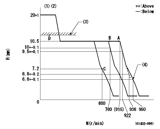
N:Pump speed
R:Rack position (mm)
(1)Target notch: K
(2)Tolerance for racks not indicated: +-0.05mm.
(3)RACK LIMIT
(4)Set idle sub-spring
----------
K=11
----------
----------
K=11
----------
Speed control lever angle
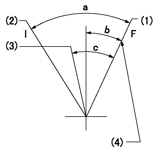
F:Full speed
I:Idle
(1)Set the pump speed at aa
(2)Stopper bolt setting
(3)When pump speed set at bb
(4)Stopper bolt setting
----------
aa=922r/min bb=760r/min
----------
a=16deg+-5deg b=3deg+-5deg c=8deg+-5deg
----------
aa=922r/min bb=760r/min
----------
a=16deg+-5deg b=3deg+-5deg c=8deg+-5deg
Stop lever angle

N:Pump normal
S:Stop the pump.
(1)Normal
----------
----------
a=7deg+-5deg b=53deg+-5deg
----------
----------
a=7deg+-5deg b=53deg+-5deg
Timing setting

(1)Pump vertical direction
(2)Position of camshaft's key groove at No 1 cylinder's beginning of injection
(3)-
(4)-
----------
----------
a=(60deg)
----------
----------
a=(60deg)
Information:
Storage Procedure
When a generator is in storage for any length of time, moisture condenses in the windings. Minimize the condensation by use of a dry storage space and space heaters. Refer to step 2 belowIf a brush-type generator (SRCR) is to be in storage for a year or more, lift the brushes off the slip ring to prevent damage to the slip ring by chemical action.After Storage
Test the main stator windings with a megohmmeter in the following situations: 1. Before initial startup of generator set.2. Every 3 months* if generator is operating in a humid environment.3. If generator has not been run under load for 3 months* or more.*This is a guideline only. It may be necessary to megger more frequently if environment is extremely humid, salty or if the last megger test was close to 1 megohm.The megohmmeter test is described in Service Manuals SENR2180 or SENR7968. A reading of 1 meghom or less indicates that the winding has absorbed too much moisture.To Remove Moisture
To remove moisture caused by high humidity, use one of the following methods to make the generator dry:1. Energize space heaters in generator if so equipped.2. Put the generator in an oven at a temperature of not more than 85°C (185°F) for four hours.
If an oven is used for drying, use a forced air type rather than a radiant type. Radiant ovens can cause localized overheating.
3. Space heaters of the same type used in marine applications, can be installed on generators. (See the Parts Book.) These heaters heat the windings to remove moisture and should be connected at all times in high humidity conditions whenever the generator is not running.4. Use a canvas enclosure around the generator and heating lamps to increase the temperature. Make an opening in the top for release of moisture.5. Send a low voltage current through the windings to increase the temperature of the windings. Do not exceed 85°C (185°F).If the megohmmeter test reads under 1 megohm after the drying or if it goes below 1 megohm shortly after drying, contact your Caterpillar dealer. The insulation has deteriorated and should be reconditioned.