Information injection-pump assembly
ZEXEL
101402-9911
1014029911
Rating:
Cross reference number
ZEXEL
101402-9911
1014029911
Zexel num
Bosch num
Firm num
Name
Calibration Data:
Adjustment conditions
Test oil
1404 Test oil ISO4113 or {SAEJ967d}
1404 Test oil ISO4113 or {SAEJ967d}
Test oil temperature
degC
40
40
45
Nozzle and nozzle holder
105780-8140
Bosch type code
EF8511/9A
Nozzle
105780-0000
Bosch type code
DN12SD12T
Nozzle holder
105780-2080
Bosch type code
EF8511/9
Opening pressure
MPa
17.2
Opening pressure
kgf/cm2
175
Injection pipe
Outer diameter - inner diameter - length (mm) mm 6-2-600
Outer diameter - inner diameter - length (mm) mm 6-2-600
Overflow valve
131424-1520
Overflow valve opening pressure
kPa
157
123
191
Overflow valve opening pressure
kgf/cm2
1.6
1.25
1.95
Tester oil delivery pressure
kPa
157
157
157
Tester oil delivery pressure
kgf/cm2
1.6
1.6
1.6
Direction of rotation (viewed from drive side)
Right R
Right R
Injection timing adjustment
Direction of rotation (viewed from drive side)
Right R
Right R
Injection order
1-3-4-2
Pre-stroke
mm
3.2
3.15
3.25
Beginning of injection position
Drive side NO.1
Drive side NO.1
Difference between angles 1
Cal 1-3 deg. 90 89.5 90.5
Cal 1-3 deg. 90 89.5 90.5
Difference between angles 2
Cal 1-4 deg. 180 179.5 180.5
Cal 1-4 deg. 180 179.5 180.5
Difference between angles 3
Cyl.1-2 deg. 270 269.5 270.5
Cyl.1-2 deg. 270 269.5 270.5
Injection quantity adjustment
Adjusting point
A
Rack position
8.9
Pump speed
r/min
1500
1500
1500
Average injection quantity
mm3/st.
89
88
90
Max. variation between cylinders
%
0
-2
2
Basic
*
Fixing the lever
*
Boost pressure
kPa
68
68
Boost pressure
mmHg
510
510
Injection quantity adjustment_02
Adjusting point
D
Rack position
7.2+-0.5
Pump speed
r/min
350
350
350
Average injection quantity
mm3/st.
8
6.5
9.5
Max. variation between cylinders
%
0
-14
14
Fixing the rack
*
Boost pressure
kPa
0
0
0
Boost pressure
mmHg
0
0
0
Injection quantity adjustment_03
Adjusting point
E
Rack position
-
Pump speed
r/min
100
100
100
Average injection quantity
mm3/st.
90
90
106
Fixing the lever
*
Boost pressure
kPa
0
0
0
Boost pressure
mmHg
0
0
0
Rack limit
*
Boost compensator adjustment
Pump speed
r/min
600
600
600
Rack position
R1-1.35
Boost pressure
kPa
13.3
10.6
16
Boost pressure
mmHg
100
80
120
Boost compensator adjustment_02
Pump speed
r/min
600
600
600
Rack position
R1(8.9)
Boost pressure
kPa
54.7
48
61.4
Boost pressure
mmHg
410
360
460
Test data Ex:
Governor adjustment
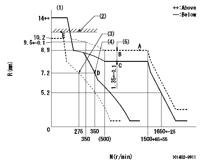
N:Pump speed
R:Rack position (mm)
(1)Target notch: K
(2)RACK LIMIT
(3)Set idle sub-spring
(4)Main spring setting
(5)Boost compensator stroke
----------
K=6
----------
----------
K=6
----------
Speed control lever angle
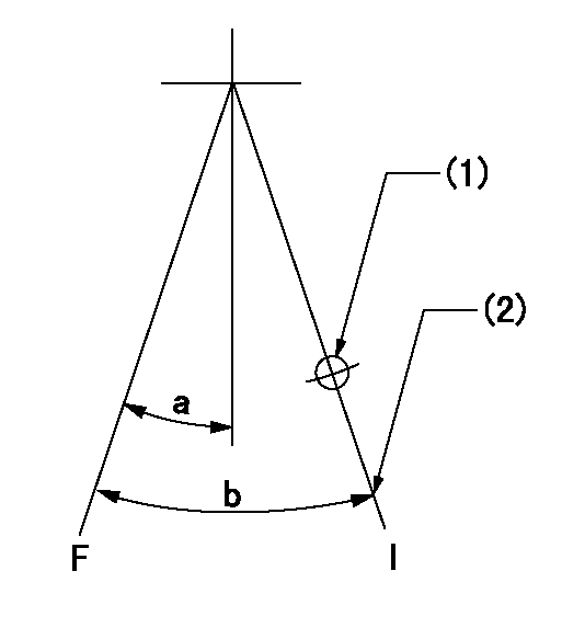
F:Full speed
I:Idle
(1)Use the hole at R = aa
(2)Stopper bolt setting
----------
aa=70mm
----------
a=(7deg)+-5deg b=(24deg)+-5deg
----------
aa=70mm
----------
a=(7deg)+-5deg b=(24deg)+-5deg
Stop lever angle
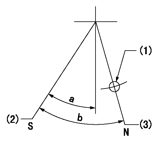
N:Pump normal
S:Stop the pump.
(1)Use the hole at R = aa
(2)Speed = bb, rack position = cc (sealed at delivery)
(3)Normal
----------
aa=40mm bb=0r/min cc=1-0.5mm
----------
a=44.5deg+-5deg b=(50deg)
----------
aa=40mm bb=0r/min cc=1-0.5mm
----------
a=44.5deg+-5deg b=(50deg)
Timing setting

(1)Pump vertical direction
(2)Position of gear mark 'CC' at No 1 cylinder's beginning of injection
(3)B.T.D.C.: aa
(4)-
----------
aa=18deg
----------
a=(90deg)
----------
aa=18deg
----------
a=(90deg)
Information:
Cooling
Never add coolant to an overheated engine; allow the engine to cool first.Check specific gravity of antifreeze solution frequently in cold weather to assure adequate protection.Coolant should be drained and replaced "Every 2000 Service Meter Units." With additions of Caterpillar Cooling System Inhibitor or the use of Coolant Conditioner Elements as recommended, the drain period can be extended to "Every 4000 Service Meter Units."All water is corrosive at engine operating temperature. The cooling system should be protected with inhibitor at all times regardless of concentration of antifreeze. This can be done by maintaining a 3% concentration of liquid Caterpillar Cooling System Inhibitor or by using Coolant Conditioner Elements.Never use both the liquid cooling system inhibitor and coolant elements at the same time.Do not use Caterpillar Cooling System Inhibitor or Coolant Conditioner Elements with Dowtherm 209 Full-Fill Coolant.
Whenever draining and refilling cooling system, always recheck the coolant level when the engine reaches normal operating temperature.Filling at over 5 U.S. gallons (19 liters) per minute can cause air pockets in the cooling system.Premix antifreeze solution to provide protection to the lowest expected ambient temperature. Pure undiluted antifreeze will freeze at -10°F (-23°C).Operate with a thermostat in the cooling system all year-round. Cooling system problems can arise without a thermostat.Electrical
When using jumper cables to start the engine, be sure to connect in parallel: POSITIVE (+) to POSITIVE (+) and NEGATIVE (-) to NEGATIVE (-).
Scheduled Oil Sampling
Use Scheduled Oil Sampling to monitor the engine's condition and maintenance requirements.Each oil sample should be taken when the oil is hot, and well mixed, to insure a sample which is representative of the oil in the compartment.Consult your Caterpillar dealer for complete information, and assistance in establishing a Scheduled Oil Sampling program for your equipment.Fuel
Fill fuel tank at the end of each day of operation to drive out moisture laden air and to prevent condensation. Do not fill the tank to the brim. The fuel expands when it gets warm and may overflow.
Water and sediment should be drained from the fuel tank at the start of each shift or after the fuel tank has been filled and allowed to stand for 5 to 10 minutes.Drain fuel tank of moisture and sediment as required by prevailing conditions.After changing fuel filters, always bleed fuel system to remove air bubbles from system.Air Intake
Service air cleaners when RED band in indicator locks in visible position.