Information injection-pump assembly
BOSCH
9 400 614 034
9400614034
ZEXEL
101402-9910
1014029910
Rating:
Service parts 101402-9910 INJECTION-PUMP ASSEMBLY:
1.
_
5.
AUTOM. ADVANCE MECHANIS
6.
COUPLING PLATE
8.
_
9.
_
11.
Nozzle and Holder
12.
Open Pre:MPa(Kqf/cm2)
19.6{200}
15.
NOZZLE SET
Cross reference number
BOSCH
9 400 614 034
9400614034
ZEXEL
101402-9910
1014029910
Zexel num
Bosch num
Firm num
Name
101402-9910
9 400 614 034
INJECTION-PUMP ASSEMBLY
DB33TI 14BC INJECTION PUMP ASSY PE4A,5A, PE
DB33TI 14BC INJECTION PUMP ASSY PE4A,5A, PE
9 400 614 034
DAEWOO
INJECTION-PUMP ASSEMBLY
DB33TI * K 14BC INJECTION PUMP ASSY PE4A,5A, PE
DB33TI * K 14BC INJECTION PUMP ASSY PE4A,5A, PE
Calibration Data:
Adjustment conditions
Test oil
1404 Test oil ISO4113 or {SAEJ967d}
1404 Test oil ISO4113 or {SAEJ967d}
Test oil temperature
degC
40
40
45
Nozzle and nozzle holder
105780-8140
Bosch type code
EF8511/9A
Nozzle
105780-0000
Bosch type code
DN12SD12T
Nozzle holder
105780-2080
Bosch type code
EF8511/9
Opening pressure
MPa
17.2
Opening pressure
kgf/cm2
175
Injection pipe
Outer diameter - inner diameter - length (mm) mm 6-2-600
Outer diameter - inner diameter - length (mm) mm 6-2-600
Overflow valve
131424-1520
Overflow valve opening pressure
kPa
157
123
191
Overflow valve opening pressure
kgf/cm2
1.6
1.25
1.95
Tester oil delivery pressure
kPa
157
157
157
Tester oil delivery pressure
kgf/cm2
1.6
1.6
1.6
Direction of rotation (viewed from drive side)
Right R
Right R
Injection timing adjustment
Direction of rotation (viewed from drive side)
Right R
Right R
Injection order
1-3-4-2
Pre-stroke
mm
3.2
3.15
3.25
Beginning of injection position
Drive side NO.1
Drive side NO.1
Difference between angles 1
Cal 1-3 deg. 90 89.5 90.5
Cal 1-3 deg. 90 89.5 90.5
Difference between angles 2
Cal 1-4 deg. 180 179.5 180.5
Cal 1-4 deg. 180 179.5 180.5
Difference between angles 3
Cyl.1-2 deg. 270 269.5 270.5
Cyl.1-2 deg. 270 269.5 270.5
Injection quantity adjustment
Adjusting point
A
Rack position
8.4
Pump speed
r/min
1500
1500
1500
Average injection quantity
mm3/st.
75
74
76
Max. variation between cylinders
%
0
-2
2
Basic
*
Fixing the lever
*
Boost pressure
kPa
66.7
66.7
Boost pressure
mmHg
500
500
Injection quantity adjustment_02
Adjusting point
D
Rack position
7.2+-0.5
Pump speed
r/min
350
350
350
Average injection quantity
mm3/st.
8
6.5
9.5
Max. variation between cylinders
%
0
-14
14
Fixing the rack
*
Boost pressure
kPa
0
0
0
Boost pressure
mmHg
0
0
0
Injection quantity adjustment_03
Adjusting point
E
Rack position
-
Pump speed
r/min
100
100
100
Average injection quantity
mm3/st.
100
100
116
Fixing the lever
*
Boost pressure
kPa
0
0
0
Boost pressure
mmHg
0
0
0
Rack limit
*
Boost compensator adjustment
Pump speed
r/min
600
600
600
Rack position
R1-0.6
Boost pressure
kPa
13.3
10.6
16
Boost pressure
mmHg
100
80
120
Boost compensator adjustment_02
Pump speed
r/min
600
600
600
Rack position
R1(8.4)
Boost pressure
kPa
53.3
46.6
60
Boost pressure
mmHg
400
350
450
Test data Ex:
Governor adjustment
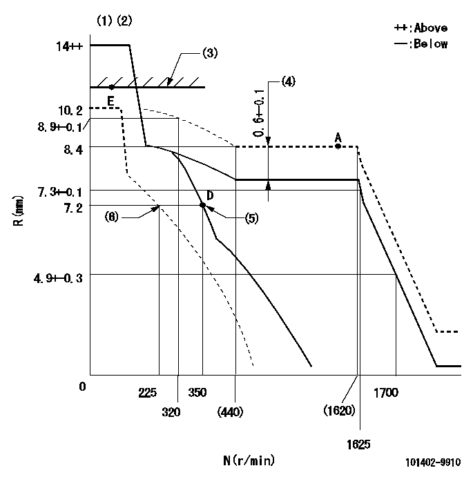
N:Pump speed
R:Rack position (mm)
(1)Target notch: K
(2)Tolerance for racks not indicated: +-0.05mm.
(3)RACK LIMIT
(4)Boost compensator stroke
(5)Main spring setting
(6)Set idle sub-spring
----------
K=5
----------
----------
K=5
----------
Speed control lever angle
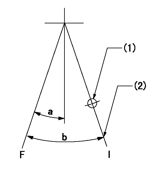
F:Full speed
I:Idle
(1)Use the hole at R = aa
(2)Stopper bolt setting
----------
aa=70mm
----------
a=(11deg)+-5deg b=(25deg)+-5deg
----------
aa=70mm
----------
a=(11deg)+-5deg b=(25deg)+-5deg
Stop lever angle
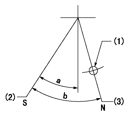
N:Pump normal
S:Stop the pump.
(1)Use the hole at R = aa
(2)Speed = bb, rack position = cc (sealed at delivery)
(3)Normal
----------
aa=40mm bb=0r/min cc=1-0.5mm
----------
a=44.5deg+-5deg b=(50deg)
----------
aa=40mm bb=0r/min cc=1-0.5mm
----------
a=44.5deg+-5deg b=(50deg)
Timing setting

(1)Pump vertical direction
(2)Position of gear mark 'CC' at No 1 cylinder's beginning of injection
(3)B.T.D.C.: aa
(4)-
----------
aa=18deg
----------
a=(100deg)
----------
aa=18deg
----------
a=(100deg)
Information:
When the preset temperature, pressure or fluid level occurs, either a light or an audible alarm will be energized. The light or alarm will continue to operate until the condition is corrected. When the condition is corrected the alarm will automatically reset and the light will turn off.
The cause of the shutdown must be investigated and corrected before starting and operating the engine.
Testing Indicator Lights
Most control panels are equipped with a test switch. By turning the switch ON, all of the indicator lights can be checked for proper operation. Test the indicator lights periodically, replace burned out light bulbs immediately.Alarm Shutoff Switch
A switch may be installed in the alarm circuit for silencing the alarm while the engine is stopped for repairs. Be sure the switch is moved to the closed (ON) position and the warning lights are lit before starting.
Place switch in the closed (ON) position when the engine is started, so the engine will be protected.
Output Shaft Governor Operation
When the load can overspeed the torque converter output shaft, an output shaft governor should be installed. The output shaft governor is a speed limiting device which automatically adjusts engine governor setting according to load requirement.Determining Cause Of Shutdown
If the engine has been shutdown by a safety device, do not start the engine and place it into service without having the cause of the shutdown investigated and corrected.
Low Oil Pressure Checks
If the low oil pressure shutoff control has stopped the engine, make the following checks: 1. Check the water temperature gauge. Determine if the engine was overheated. Check for external water leaks.
Beware of steam or scalding water. Do not attempt to loosen the radiator cap until the temperature gauge indicates the coolant has sufficiently cooled. Then, loosen the cap slowly.
2. Check the oil level. Oil level must be between the ADD and FULL marks on the side of the dipstick stamped CHECK WITH ENGINE STOPPED.3. If the oil level is below the ADD mark, check for oil spray and/or oil accumulations. If any are found, have the necessary repairs made. Before starting, add oil to the FULL mark.4. Reset the shutoff control.5. Remove the load and start the engine at its slowest speed. Be prepared to shut the engine down manually.6. Be alert for unusual sounds or noises. If the engine knocks, stop the engine immediately and call your Caterpillar dealer.7. If the engine blows excessive black exhaust or has excessive crankcase blow-by, the engine may need reconditioning. Stop the engine and call your Caterpillar dealer.8. If the engine runs satisfactorily, observe the oil pressure gauge. If satisfactory pressure is not indicated, shut the engine down; call your Caterpillar dealer.9. If proper oil pressure is registered, check to see if the reset knob has moved to the run position. If the knob does not move, stop the engine. Check the shutoff control, the oil line, and the oil pressure gauge. Have necessary repairs made.10. If the oil pressure gauge registers normal oil pressure, if the knob on the shutoff
Have questions with 101402-9910?
Group cross 101402-9910 ZEXEL
Daewoo
101402-9910
9 400 614 034
INJECTION-PUMP ASSEMBLY
DB33TI
DB33TI