Information injection-pump assembly
BOSCH
9 400 614 033
9400614033
ZEXEL
101402-9900
1014029900
Rating:
Service parts 101402-9900 INJECTION-PUMP ASSEMBLY:
1.
_
5.
AUTOM. ADVANCE MECHANIS
6.
COUPLING PLATE
8.
_
9.
_
11.
Nozzle and Holder
12.
Open Pre:MPa(Kqf/cm2)
19.6{200}
15.
NOZZLE SET
Cross reference number
BOSCH
9 400 614 033
9400614033
ZEXEL
101402-9900
1014029900
Zexel num
Bosch num
Firm num
Name
101402-9900
9 400 614 033
INJECTION-PUMP ASSEMBLY
DB33TI 14BC INJECTION PUMP ASSY PE4A,5A, PE
DB33TI 14BC INJECTION PUMP ASSY PE4A,5A, PE
9 400 614 033
DAEWOO
INJECTION-PUMP ASSEMBLY
DB33TI * K 14BC INJECTION PUMP ASSY PE4A,5A, PE
DB33TI * K 14BC INJECTION PUMP ASSY PE4A,5A, PE
Calibration Data:
Adjustment conditions
Test oil
1404 Test oil ISO4113 or {SAEJ967d}
1404 Test oil ISO4113 or {SAEJ967d}
Test oil temperature
degC
40
40
45
Nozzle and nozzle holder
105780-8140
Bosch type code
EF8511/9A
Nozzle
105780-0000
Bosch type code
DN12SD12T
Nozzle holder
105780-2080
Bosch type code
EF8511/9
Opening pressure
MPa
17.2
Opening pressure
kgf/cm2
175
Injection pipe
Outer diameter - inner diameter - length (mm) mm 6-2-600
Outer diameter - inner diameter - length (mm) mm 6-2-600
Overflow valve
131424-1520
Overflow valve opening pressure
kPa
157
123
191
Overflow valve opening pressure
kgf/cm2
1.6
1.25
1.95
Tester oil delivery pressure
kPa
157
157
157
Tester oil delivery pressure
kgf/cm2
1.6
1.6
1.6
Direction of rotation (viewed from drive side)
Right R
Right R
Injection timing adjustment
Direction of rotation (viewed from drive side)
Right R
Right R
Injection order
1-3-4-2
Pre-stroke
mm
3.2
3.15
3.25
Beginning of injection position
Drive side NO.1
Drive side NO.1
Difference between angles 1
Cal 1-3 deg. 90 89.5 90.5
Cal 1-3 deg. 90 89.5 90.5
Difference between angles 2
Cal 1-4 deg. 180 179.5 180.5
Cal 1-4 deg. 180 179.5 180.5
Difference between angles 3
Cyl.1-2 deg. 270 269.5 270.5
Cyl.1-2 deg. 270 269.5 270.5
Injection quantity adjustment
Adjusting point
A
Rack position
9.1
Pump speed
r/min
900
900
900
Average injection quantity
mm3/st.
76.5
75.5
77.5
Max. variation between cylinders
%
0
-2
2
Basic
*
Fixing the rack
*
Injection quantity adjustment_02
Adjusting point
D
Rack position
7.8+-0.5
Pump speed
r/min
345
345
345
Average injection quantity
mm3/st.
14
12.5
15.5
Max. variation between cylinders
%
0
-14
14
Fixing the rack
*
Injection quantity adjustment_03
Adjusting point
E
Rack position
-
Pump speed
r/min
100
100
100
Average injection quantity
mm3/st.
100
100
116
Fixing the lever
*
Rack limit
*
Test data Ex:
Governor adjustment
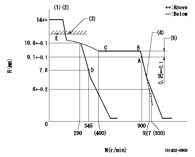
N:Pump speed
R:Rack position (mm)
(1)Target notch: K
(2)Tolerance for racks not indicated: +-0.05mm.
(3)RACK LIMIT
(4)Idle sub spring setting: L1.
(5)Rack difference between N = N1 and N = N2
----------
K=12 L1=6.4+-0.1mm N1=900r/min N2=875r/min
----------
----------
K=12 L1=6.4+-0.1mm N1=900r/min N2=875r/min
----------
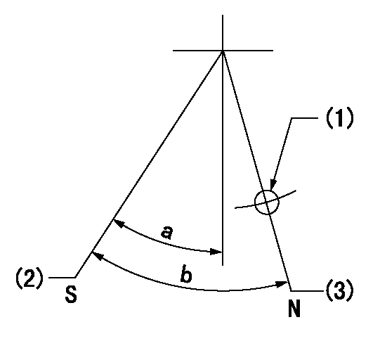
Speed control lever angle

F:Full speed
I:Idle
(1)Stopper bolt setting
----------
----------
a=2deg+-5deg b=21deg+-5deg
----------
----------
a=2deg+-5deg b=21deg+-5deg
Stop lever angle
N:Pump normal
S:Stop the pump.
(1)Use the hole at R = aa
(2)Speed = bb, rack position = cc (sealed at delivery)
(3)Normal
----------
aa=40mm bb=0r/min cc=1-0.5mm
----------
a=44.5deg+-5deg b=(50deg)
----------
aa=40mm bb=0r/min cc=1-0.5mm
----------
a=44.5deg+-5deg b=(50deg)
Timing setting

(1)Pump vertical direction
(2)Position of gear mark 'CC' at No 1 cylinder's beginning of injection
(3)B.T.D.C.: aa
(4)-
----------
aa=13deg
----------
a=(90deg)
----------
aa=13deg
----------
a=(90deg)
Information:
After the engine starts, and at frequent intervals while the engine is operating, the gauges should be observed. Determine the normal reading for each gauge. Investigate the cause whenever there is a significant change in the reading.Gauges
Tachometer
The tachometer indicates engine RPM. The high idle RPM and the full load RPM are stamped on the engine's information plate. The engine can be operated between these two speed limits for long periods of time without shortening engine life. Prolonged operation at high idle with little or no load can cause adverse engine operation. Engine Oil Pressure
If the gauge reading fluctuates after the load is stable:1. Remove the load.2. Reduce engine speed to low idle.3. Observe the oil level. Maintain the oil level between the ADD and FULL mark on the dipstick. If the reading continues to fluctuate when the oil level is correct, stop engine and call your Caterpillar dealer. Engine Jacket Water Temperature
The engine should operate within the NORMAL (green) range. If the engine is operating in the (red) range and steam becomes apparent:1. Reduce the load and engine RPM.2. Inspect for coolant leaks.3. Determine if the engine must be shut down immediately; or if the engine can be safely cooled by reducing the load.See COOLING SYSTEM MAINTENANCE INSTRUCTIONS.
Do not add cold water to a hot engine: Cracking of engine components may occur. Allow the engine to cool, then add coolant.
If the temperature gauge reading registers in or near the cold range (white) while operating under load:1. Check the water temperature gauge for accuracy.2. Check the temperature regulators for proper temperature range. Replace regulators if necessary.See COOLING SYSTEM MAINTENANCE for DETAILS. Fuel pressure
If the fuel filter gauge registers in the OUT range, clean the primary fuel filter, if so equipped. Install new secondary or final fuel filter elements if gauge still registers OUT. See the FUEL MAINTENANCE INSTRUCTIONS and FUEL SPECIFICATIONS. Ammeter:
The ammeter reading is normal when the indicator is at or on the (+) side of zero, when the engine is running at rated speed. If indicator is to the left (-) side of zero, investigate and correct cause. Air Cleaner Service Indicator
When the gauge indicator locks in the red range, service the air cleaner. With the engine stopped; see AIR INDUCTION AND EXHAUST SYSTEM MAINTENANCE INSTRUCTIONS. Calibrated Gauges
Calibrated gauges are used on some engines to monitor the engine systems. If an abnormal engine condition develops, determine and analyze and correct the cause before a failure and downtime occurs.The operating limits given in the "OPERATING RANGES FOR ENGINES" chart are based on the engine running at continuous rated speed and load, after warm-up, using SAE 30, oil. If any of the gauges register at or outside the operating limits, investigate and correct any malfunction. See TROUBLESHOOTING GUIDE for guidance.
Shut the engine down if work on or around the engine is required.
DO NOT OPERATE THE ENGINE WITH THE GAUGES REGISTERING AT OR OUTSIDE THE LIMITS.
1. Tachometer.2. Left inlet manifold temperature.3. Right inlet manifold temperature.4. Left and right exhaust manifold
Have questions with 101402-9900?
Group cross 101402-9900 ZEXEL
101402-9900
9 400 614 033
INJECTION-PUMP ASSEMBLY
DB33TI
DB33TI