Information injection-pump assembly
ZEXEL
101402-9861
1014029861
Rating:
Cross reference number
ZEXEL
101402-9861
1014029861
Zexel num
Bosch num
Firm num
Name
101402-9861
INJECTION-PUMP ASSEMBLY
Calibration Data:
Adjustment conditions
Test oil
1404 Test oil ISO4113 or {SAEJ967d}
1404 Test oil ISO4113 or {SAEJ967d}
Test oil temperature
degC
40
40
45
Nozzle and nozzle holder
105780-8140
Bosch type code
EF8511/9A
Nozzle
105780-0000
Bosch type code
DN12SD12T
Nozzle holder
105780-2080
Bosch type code
EF8511/9
Opening pressure
MPa
17.2
Opening pressure
kgf/cm2
175
Injection pipe
Outer diameter - inner diameter - length (mm) mm 6-2-600
Outer diameter - inner diameter - length (mm) mm 6-2-600
Overflow valve
131424-1520
Overflow valve opening pressure
kPa
157
157
157
Overflow valve opening pressure
kgf/cm2
1.6
1.6
1.6
Tester oil delivery pressure
kPa
157
157
157
Tester oil delivery pressure
kgf/cm2
1.6
1.6
1.6
Direction of rotation (viewed from drive side)
Right R
Right R
Injection timing adjustment
Direction of rotation (viewed from drive side)
Right R
Right R
Injection order
1-3-4-2
Pre-stroke
mm
3.6
3.55
3.65
Beginning of injection position
Drive side NO.1
Drive side NO.1
Difference between angles 1
Cal 1-3 deg. 90 89.5 90.5
Cal 1-3 deg. 90 89.5 90.5
Difference between angles 2
Cal 1-4 deg. 180 179.5 180.5
Cal 1-4 deg. 180 179.5 180.5
Difference between angles 3
Cyl.1-2 deg. 270 269.5 270.5
Cyl.1-2 deg. 270 269.5 270.5
Injection quantity adjustment
Adjusting point
A
Rack position
10.6
Pump speed
r/min
1100
1100
1100
Average injection quantity
mm3/st.
45
44
46
Max. variation between cylinders
%
0
-2.5
2.5
Basic
*
Fixing the lever
*
Injection quantity adjustment_02
Adjusting point
C
Rack position
8.6+-0.5
Pump speed
r/min
450
450
450
Average injection quantity
mm3/st.
12.5
11.5
13.5
Max. variation between cylinders
%
0
-15
15
Fixing the rack
*
Injection quantity adjustment_03
Adjusting point
D
Rack position
11.5++
Pump speed
r/min
100
100
100
Average injection quantity
mm3/st.
60
55
65
Fixing the lever
*
Rack limit
*
Test data Ex:
Governor adjustment
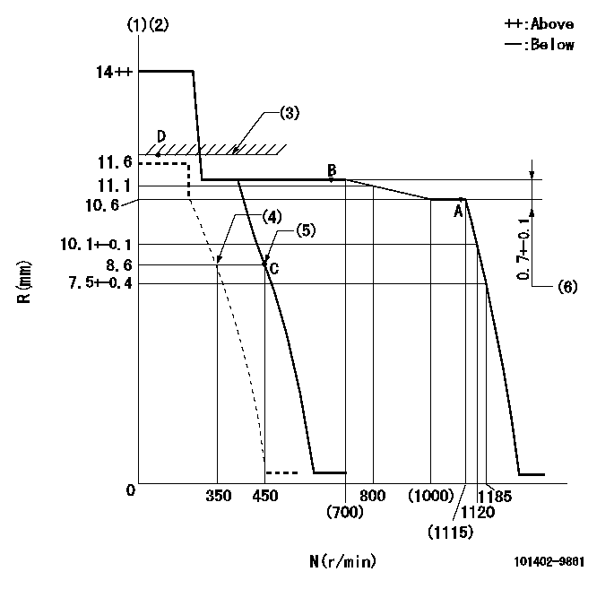
N:Pump speed
R:Rack position (mm)
(1)Target notch: K
(2)Tolerance for racks not indicated: +-0.05mm.
(3)RACK LIMIT
(4)Set idle sub-spring
(5)Main spring setting
(6)Rack difference between N = N1 and N = N2
----------
K=8 N1=1100r/min N2=650r/min
----------
----------
K=8 N1=1100r/min N2=650r/min
----------
Speed control lever angle

F:Full speed
I:Idle
(1)Stopper bolt setting
----------
----------
a=6deg+-5deg b=24deg+-5deg
----------
----------
a=6deg+-5deg b=24deg+-5deg
Stop lever angle
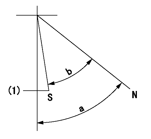
N:Pump normal
S:Stop the pump.
(1)Normal stop
----------
----------
a=58deg+-5deg b=53deg+-5deg
----------
----------
a=58deg+-5deg b=53deg+-5deg
Timing setting

(1)Pump vertical direction
(2)Position of camshaft's key groove at No 1 cylinder's beginning of injection
(3)-
(4)-
----------
----------
a=(60deg)
----------
----------
a=(60deg)
Information:
Appendix
Configuration Information
Table 7
Over-Temp
Inlet Over-Temperature Alarm
Condition Expected Value
Enable Alarm Yes
Log Alarm Transitions Yes
Active Output During Alarm Output 1
Output function ON only during alarm
Assert Alarm Above
650 °C (1202 °F)
Hysteresis
20 °C (68 °F)
Upon Over Temperature extend alarm for 60 seconds
Table 8
Over-Pres
Over-Pressure Warning
Condition Expected Value
Enable Alarm Yes
Log Alarm Transitions Yes
Active Output During Alarm Output 1
Output Function ON only during alarm
Assert Alarm when the measured pressure exceeds 7" of Hg for 5% of the time during a 60 min measurement interval
Over-Pressure Alarm
Condition Expected Value
Enable Alarm Yes
Log Alarm Transitions Yes
Active Output During Alarm Output 2
Output Function Latched ON upon alarm
Assert alarm when the measured pressure exceeds 8" of Hg for 5% of the time during a 60 min measurement interval
Table 9
TC-Fail (1)
Open Thermocouple Detect
Condition Expected Value
Enable Alarm Yes
Log Alarm Transitions Yes
Output During Alarm Output 1
Output Function Latched ON upon alarm
Assert alarm if measured temperature is above
1000 °C (1832 °F)
Shorted Thermocouple Detect
Condition Expected Value
Enable Alarm Yes
Log Alarm Transitions Yes
Output During Alarm Output 1
Output Function Latched ON upon alarm
Assert alarm if pressure is greater than 1" of Hg for 10 min and measured temperature does not exceed
120 °C (248 °F)
( 1 ) Output selection applies to both open and shorted alarms
Table 10
Pressure Sensor Fail
No Change Alarm
Condition Expected Value
Enable Alarm Yes
Log Alarm Transitions Yes
Active Outputs During Alarm Output 1
Output Function Latched ON upon Alarm
Assert alarm if exhaust temperature is above
250 °C (482 °F) for 10 min and the pressure doesn't change by at least 0.25" of Hg
Negative Pressure Alarm
Condition Expected Value
Enable Alarm Yes
Log Alarm Transitions Yes
Active Output During Alarm Output 1
Output Function Latched ON during alarm
Assert Alarm if temperature is above
200 °C (392 °F) for 10 min and the pressure is less than −1" of
Have questions with 101402-9861?
Group cross 101402-9861 ZEXEL
Yanmar
Mitsubishi-Heav
101402-9861
INJECTION-PUMP ASSEMBLY