Information injection-pump assembly
ZEXEL
101402-9860
1014029860
Rating:
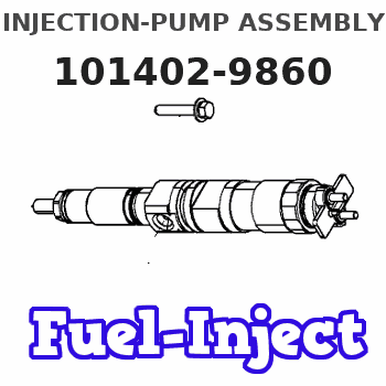
Service parts 101402-9860 INJECTION-PUMP ASSEMBLY:
1.
_

5.
AUTOM. ADVANCE MECHANIS
6.
COUPLING PLATE
7.
COUPLING PLATE
8.
_
9.
_
10.
NOZZLE AND HOLDER ASSY
11.
Nozzle and Holder
12.
Open Pre:MPa(Kqf/cm2)
13.
NOZZLE-HOLDER
14.
NOZZLE
15.
NOZZLE SET
Cross reference number
ZEXEL
101402-9860
1014029860
Zexel num
Bosch num
Firm num
Name
101402-9860
INJECTION-PUMP ASSEMBLY
4TNE98 14BC PE4A,5A, PE
4TNE98 14BC PE4A,5A, PE
Calibration Data:
Adjustment conditions
Test oil
1404 Test oil ISO4113 or {SAEJ967d}
1404 Test oil ISO4113 or {SAEJ967d}
Test oil temperature
degC
40
40
45
Nozzle and nozzle holder
105780-8140
Bosch type code
EF8511/9A
Nozzle
105780-0000
Bosch type code
DN12SD12T
Nozzle holder
105780-2080
Bosch type code
EF8511/9
Opening pressure
MPa
17.2
Opening pressure
kgf/cm2
175
Injection pipe
Outer diameter - inner diameter - length (mm) mm 6-2-600
Outer diameter - inner diameter - length (mm) mm 6-2-600
Overflow valve
131424-1520
Overflow valve opening pressure
kPa
157
123
191
Overflow valve opening pressure
kgf/cm2
1.6
1.25
1.95
Tester oil delivery pressure
kPa
157
157
157
Tester oil delivery pressure
kgf/cm2
1.6
1.6
1.6
Direction of rotation (viewed from drive side)
Right R
Right R
Injection timing adjustment
Direction of rotation (viewed from drive side)
Right R
Right R
Injection order
1-3-4-2
Pre-stroke
mm
3.6
3.55
3.65
Beginning of injection position
Drive side NO.1
Drive side NO.1
Difference between angles 1
Cal 1-3 deg. 90 89.5 90.5
Cal 1-3 deg. 90 89.5 90.5
Difference between angles 2
Cal 1-4 deg. 180 179.5 180.5
Cal 1-4 deg. 180 179.5 180.5
Difference between angles 3
Cyl.1-2 deg. 270 269.5 270.5
Cyl.1-2 deg. 270 269.5 270.5
Injection quantity adjustment
Adjusting point
A
Rack position
10.6
Pump speed
r/min
1100
1100
1100
Average injection quantity
mm3/st.
45
44
46
Max. variation between cylinders
%
0
-2.5
2.5
Basic
*
Fixing the lever
*
Injection quantity adjustment_02
Adjusting point
C
Rack position
8.6+-0.5
Pump speed
r/min
450
450
450
Average injection quantity
mm3/st.
12.5
11.5
13.5
Max. variation between cylinders
%
0
-15
15
Fixing the rack
*
Injection quantity adjustment_03
Adjusting point
D
Rack position
-
Pump speed
r/min
100
100
100
Average injection quantity
mm3/st.
60
55
65
Fixing the lever
*
Rack limit
*
Test data Ex:
Governor adjustment
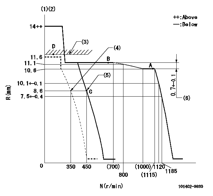
N:Pump speed
R:Rack position (mm)
(1)Target notch: K
(2)Tolerance for racks not indicated: +-0.05mm.
(3)RACK LIMIT
(4)Set idle sub-spring
(5)Main spring setting
(6)Rack difference between N = N1 and N = N2
----------
K=8 N1=1100r/min N2=650r/min
----------
----------
K=8 N1=1100r/min N2=650r/min
----------
Speed control lever angle
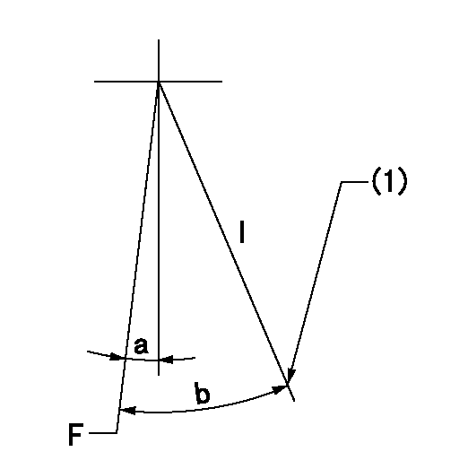
F:Full speed
I:Idle
(1)Stopper bolt setting
----------
----------
a=6deg+-5deg b=24deg+-5deg
----------
----------
a=6deg+-5deg b=24deg+-5deg
Stop lever angle
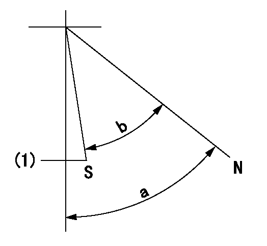
N:Pump normal
S:Stop the pump.
(1)At delivery
----------
----------
a=58deg+-5deg b=53deg+-5deg
----------
----------
a=58deg+-5deg b=53deg+-5deg
Timing setting

(1)Pump vertical direction
(2)Position of camshaft's key groove at No 1 cylinder's beginning of injection
(3)-
(4)-
----------
----------
a=(60deg)
----------
----------
a=(60deg)
Information:
7. Remove inner fuel lines (13). 8. Remove Jacobs washers (14) and Jacobs shims (15) from the Jacobs stud assemblies. 9. Remove bolt (17) and two Jacobs stud assemblies (16) that hold the rocker shaft assembly to the head. Remove rocker shaft assembly (18). 10. Remove Jacobs exhaust valve bridges (20) from the exhaust valves only. The intake valves have the Caterpillar intake valve bridges. Remove the Caterpillar intake valve bridges (19).Install Jacobs Engine Brake
Do each step for each end of the engine. The front half is shown.1. Put clean engine oil on the bridges and dowels.2. Install Jacobs exhaust valve bridges (20) and the Caterpillar intake valve bridges (19) on the dowels.3. Keep hand pressure on the bridges, and turn the adjustment screw clockwise until contact is made with the valve stem. Turn the screw an extra 20 ° to 30 °. This will make the dowel straight in the guide and compensate for gap (slack) in the threads. Hold the adjustment screw in this position, and tighten the locknut to a torque of 28 4 N m (21 3 lb.ft.). 4. Put rocker shaft assembly (18) in position on the cylinder head. 5. Install Jacobs washers (21) on the Jacobs stud assemblies (16). Put clean oil on the threads, and install washer and bolt (17) and Jacobs stud assemblies (16). Tighten the center bolt and Jacobs stud assemblies in increments of 70 N m (50 lb.ft.) each until a final torque of 450 N m (330 lb.ft.) is obtained.6. Make an adjustment to the valves to have a clearance of .015 (0.38 mm) for the intake valves and .030 (0.76 mm) for the exhaust valves. Tighten the locknuts to a torque of 28 4 N m (21 3 lb.ft.), and check the valve clearance again. See Testing And Adjusting for the correct procedure. 7. Install a new Jacobs O-ring seal (22) on the Jacobs oil supply adapter in the rocker shaft assembly. Put clean oil on the Jacobs O-ring seal.
Do not cause damage to the O-ring seals on the inner fuel lines.
8. Install inner fuel lines (13). Tighten the fuel line nuts to a torque of 40 7 N m (30 5 lb.ft.) with tooling (A) and (B). The Jacobs brake for the 3406B Truck Engine has only one support bracket (11).9. Put Jacobs support brackets (11) in position as shown. Put oil on the threads of Jacobs bolts (12). Install the washers on the Jacobs bolts. Install Jacobs bolts (12) that hold the Jacobs support bracket in place. Tighten the Jacobs bolts to a torque of 450 N m (330 lb.ft.). 10. Install Jacobs washers (14) on the Jacobs stud assemblies.
Be extra careful not to cause damage to the Jacobs oil supply adapter O-ring seal when the Jacobs brake housing assembly is installed.
The brake housing assembly with the mark "FRONT" on it must
Have questions with 101402-9860?
Group cross 101402-9860 ZEXEL
Yanmar
Mitsubishi-Heav
101402-9860
INJECTION-PUMP ASSEMBLY
4TNE98
4TNE98