Information injection-pump assembly
BOSCH
9 400 614 030
9400614030
ZEXEL
101402-9830
1014029830
MITSUBISHI-HEAV
3426103090
3426103090
Rating:
Include in #1:
101602-9802
as _
Cross reference number
BOSCH
9 400 614 030
9400614030
ZEXEL
101402-9830
1014029830
MITSUBISHI-HEAV
3426103090
3426103090
Zexel num
Bosch num
Firm num
Name
101402-9830
9 400 614 030
3426103090 MITSUBISHI-HEAV
INJECTION-PUMP ASSEMBLY
S4K-T K
S4K-T K
Calibration Data:
Adjustment conditions
Test oil
1404 Test oil ISO4113 or {SAEJ967d}
1404 Test oil ISO4113 or {SAEJ967d}
Test oil temperature
degC
40
40
45
Nozzle and nozzle holder
105780-8140
Bosch type code
EF8511/9A
Nozzle
105780-0000
Bosch type code
DN12SD12T
Nozzle holder
105780-2080
Bosch type code
EF8511/9
Opening pressure
MPa
17.2
Opening pressure
kgf/cm2
175
Injection pipe
Outer diameter - inner diameter - length (mm) mm 6-2-600
Outer diameter - inner diameter - length (mm) mm 6-2-600
Overflow valve
131424-5720
Overflow valve opening pressure
kPa
255
221
289
Overflow valve opening pressure
kgf/cm2
2.6
2.25
2.95
Tester oil delivery pressure
kPa
157
157
157
Tester oil delivery pressure
kgf/cm2
1.6
1.6
1.6
Direction of rotation (viewed from drive side)
Right R
Right R
Injection timing adjustment
Direction of rotation (viewed from drive side)
Right R
Right R
Injection order
1-3-4-2
Pre-stroke
mm
3.2
3.15
3.25
Beginning of injection position
Drive side NO.1
Drive side NO.1
Difference between angles 1
Cal 1-3 deg. 90 89.5 90.5
Cal 1-3 deg. 90 89.5 90.5
Difference between angles 2
Cal 1-4 deg. 180 179.5 180.5
Cal 1-4 deg. 180 179.5 180.5
Difference between angles 3
Cyl.1-2 deg. 270 269.5 270.5
Cyl.1-2 deg. 270 269.5 270.5
Injection quantity adjustment
Adjusting point
A
Rack position
9.2
Pump speed
r/min
1100
1100
1100
Average injection quantity
mm3/st.
80.5
79.5
81.5
Max. variation between cylinders
%
0
-2.5
2.5
Basic
*
Fixing the lever
*
Injection quantity adjustment_02
Adjusting point
C
Rack position
6+-0.5
Pump speed
r/min
450
450
450
Average injection quantity
mm3/st.
11.5
10.2
12.8
Max. variation between cylinders
%
0
-14
14
Fixing the rack
*
Injection quantity adjustment_03
Adjusting point
D
Rack position
9.9++
Pump speed
r/min
100
100
100
Average injection quantity
mm3/st.
85
85
90
Fixing the lever
*
Rack limit
*
Test data Ex:
Governor adjustment
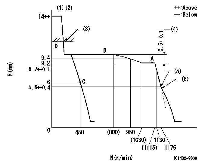
N:Pump speed
R:Rack position (mm)
(1)Target notch: K
(2)Tolerance for racks not indicated: +-0.05mm.
(3)RACK LIMIT
(4)Rack difference between N = N1 and N = N2
(5)Main spring setting
(6)Idle sub spring setting: L1.
----------
K=11 N1=1100r/min N2=700r/min L1=5.6-0.5mm
----------
----------
K=11 N1=1100r/min N2=700r/min L1=5.6-0.5mm
----------
Speed control lever angle

F:Full speed
I:Idle
(1)Stopper bolt setting
----------
----------
a=20deg+-5deg b=5deg+-5deg
----------
----------
a=20deg+-5deg b=5deg+-5deg
Stop lever angle
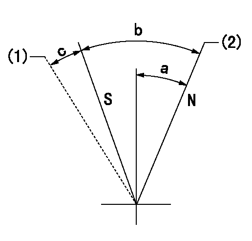
N:Pump normal
S:Stop the pump.
(1)Hold the boss against the stop side
(2)Normal
----------
----------
a=26.5deg+-5deg b=53deg+-5deg c=(11deg)
----------
----------
a=26.5deg+-5deg b=53deg+-5deg c=(11deg)
Timing setting

(1)Pump vertical direction
(2)Position of camshaft's key groove at No 1 cylinder's beginning of injection
(3)-
(4)-
----------
----------
a=(50deg)
----------
----------
a=(50deg)
Information:
Do not disconnect any air lines until the air pressure is zero.
1. Loosen the bleed valves and release the air pressure in the air tanks.2. Drain the oil from the oil pan. 3. Remove two short bolts (1) and two longer bolts (3) from manifold (2) and the BrakeSaver housing. Remove manifold (2). Remove the O-ring seals from the manifold. 4. Remove oil temperature sensing unit (4) from the BrakeSaver control valve.5. Disconnect air line (5) and hose assembly (6) from the BrakeSaver control valve. 6. Remove bolt (7) and retainer (8) that hold the oil lines in the BrakeSaver control valve. 7. Disconnect oil lines (9) and (10) from the oil cooler. Remove oil lines (9) and (10) from the BrakeSaver control valve. 8. Remove bolts (12) and BrakeSaver control valve (11) from under the oil pan. The weight is 22 kg (48 lb.).9. Remove elbow (13) from the BrakeSaver control valve. Remove the O-ring seals. The following steps are for installation of the BrakeSaver control valve.10. Inspect the O-ring seals for damage, and make replacements if needed. Put clean engine oil on the O-ring seals.11. Install the O-ring seals and elbow (13) on the BrakeSaver control valve.12. Make sure the O-ring seals are in position on the face of the BrakeSaver control valve. Put BrakeSaver control valve (11) in position under the oil pan. Install bolts (12) that hold the BrakeSaver control valve to the oil pan.13. Install oil temperature sensing unit (4) in the BrakeSaver control valve.14. Connect air line (5) and hose assembly (6) to the BrakeSaver control valve.15. Install the O-ring seals on manifold (2). Install manifold (2) in the BrakeSaver control valve. Install the four bolts that hold the manifold to the BrakeSaver housing.16. Make sure the O-ring seals are in place on the oil lines, and install oil lines (9) and (10).17. Install retainer (8) to hold the oil lines in the BrakeSaver control valve. If the bottom plug in the oil pan was removed, put the split (seam) of the gasket for the plug against the oil pan. If either plug on the side of the oil pan was removed, put 5P3413 Pipe Sealant With Teflon on the threads, and tighten the plug to a torque of 80 11 N m (60 8 lb.ft.).18. Fill the engine with oil to the correct level. See the Maintenance Manual.Disassemble & Assemble BrakeSaver Control Valve
Start By:a. remove BrakeSaver control valve 1. Remove O-ring seals (1) from the valve body.
Covers (3) and (4) hold a spring under compression. To prevent possible personal injury from flying parts, hold covers (3) and (4) when the bolts are removed.
2. Remove four bolts (2) slowly and evenly from cover (4). Remove the cover.3. Remove cover (3) and the seal from the opposite end of the valve body. 4. Remove spool (8) as an assembly.5. Remove spring (7), stop (10), spring (6) and slug (9).6. Remove the O-ring seals and sleeve (5). 7. Remove bolt (11), plate
Have questions with 101402-9830?
Group cross 101402-9830 ZEXEL
Yanmar
Mitsubishi-Heav
101402-9830
9 400 614 030
3426103090
INJECTION-PUMP ASSEMBLY
S4K-T
S4K-T