Information injection-pump assembly
ZEXEL
101402-9760
1014029760

Rating:
Cross reference number
ZEXEL
101402-9760
1014029760
Zexel num
Bosch num
Firm num
Name
101402-9760
INJECTION-PUMP ASSEMBLY
Calibration Data:
Adjustment conditions
Test oil
1404 Test oil ISO4113 or {SAEJ967d}
1404 Test oil ISO4113 or {SAEJ967d}
Test oil temperature
degC
40
40
45
Nozzle and nozzle holder
105780-8140
Bosch type code
EF8511/9A
Nozzle
105780-0000
Bosch type code
DN12SD12T
Nozzle holder
105780-2080
Bosch type code
EF8511/9
Opening pressure
MPa
17.2
Opening pressure
kgf/cm2
175
Injection pipe
Outer diameter - inner diameter - length (mm) mm 6-2-600
Outer diameter - inner diameter - length (mm) mm 6-2-600
Overflow valve
131424-1520
Overflow valve opening pressure
kPa
157
123
191
Overflow valve opening pressure
kgf/cm2
1.6
1.25
1.95
Tester oil delivery pressure
kPa
157
157
157
Tester oil delivery pressure
kgf/cm2
1.6
1.6
1.6
Direction of rotation (viewed from drive side)
Right R
Right R
Injection timing adjustment
Direction of rotation (viewed from drive side)
Right R
Right R
Injection order
1-3-4-2
Pre-stroke
mm
3.6
3.55
3.65
Beginning of injection position
Drive side NO.1
Drive side NO.1
Difference between angles 1
Cal 1-3 deg. 90 89.5 90.5
Cal 1-3 deg. 90 89.5 90.5
Difference between angles 2
Cal 1-4 deg. 180 179.5 180.5
Cal 1-4 deg. 180 179.5 180.5
Difference between angles 3
Cyl.1-2 deg. 270 269.5 270.5
Cyl.1-2 deg. 270 269.5 270.5
Injection quantity adjustment
Adjusting point
A
Rack position
10.6
Pump speed
r/min
1500
1500
1500
Average injection quantity
mm3/st.
87
86
88
Max. variation between cylinders
%
0
-3.5
3.5
Basic
*
Fixing the lever
*
Injection quantity adjustment_02
Adjusting point
B
Rack position
8.1+-0.5
Pump speed
r/min
450
450
450
Average injection quantity
mm3/st.
8
6
10
Max. variation between cylinders
%
0
-10
10
Fixing the rack
*
Injection quantity adjustment_03
Adjusting point
C
Rack position
-
Pump speed
r/min
100
100
100
Average injection quantity
mm3/st.
85
85
95
Fixing the lever
*
Rack limit
*
Test data Ex:
Governor adjustment

N:Pump speed
R:Rack position (mm)
(1)Target notch: K
(2)Tolerance for racks not indicated: +-0.05mm.
(3)RACK LIMIT
(4)Set idle sub-spring
(5)Main spring setting
----------
K=14
----------
----------
K=14
----------
Speed control lever angle
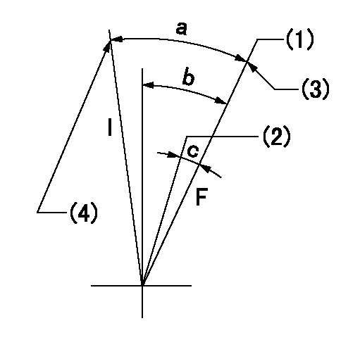
F:Full speed
I:Idle
(1)Set the pump speed at aa. ( At delivery )
(2)When pump speed set at bb
(3)Stopper bolt setting
(4)Stopper bolt setting
----------
aa=1825r/min bb=1525r/min
----------
a=32deg+-5deg b=27deg+-5deg c=9deg+-5deg
----------
aa=1825r/min bb=1525r/min
----------
a=32deg+-5deg b=27deg+-5deg c=9deg+-5deg
Stop lever angle

N:Pump normal
S:Stop the pump.
----------
----------
a=12deg+-5deg b=53deg+-5deg
----------
----------
a=12deg+-5deg b=53deg+-5deg
0000001501 GOV FULL LOAD ADJUSTMENT
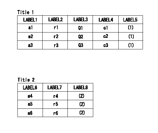
Title1:Full load stopper adjustment
Title2:Governor set speed
LABEL1:Distinguishing
LABEL2:Pump speed (r/min)
LABEL3:Ave. injection quantity (mm3/st)
LABEL4:Max. var. bet. cyl.
LABEL5:Remarks
LABEL6:Distinguishing
LABEL7:Governor set speed (r/min)
LABEL8:Remarks
(1)Adjustment conditions are the same as those for measuring injection quantity.
(2)-
----------
----------
a1=A a2=B a3=C r1=1500r/min r2=1500r/min r3=1500r/min Q1=- Q2=87+-1mm3/st Q3=- c1=- c2=+-3.5% c3=- a4=36 a5=30 a6=- r4=1800r/min r5=1500r/min r6=-
----------
----------
a1=A a2=B a3=C r1=1500r/min r2=1500r/min r3=1500r/min Q1=- Q2=87+-1mm3/st Q3=- c1=- c2=+-3.5% c3=- a4=36 a5=30 a6=- r4=1800r/min r5=1500r/min r6=-
Timing setting

(1)Pump vertical direction
(2)Position of gear mark 'ZZ' at No 1 cylinder's beginning of injection
(3)B.T.D.C.: aa
(4)-
----------
aa=16deg
----------
a=(100deg)
----------
aa=16deg
----------
a=(100deg)
Information:
2. Loosen the clamps on breather tube (1), and pull it back for clearance. 3. Remove bolt (2) from the cover on the side of the cylinder block. 4. Remove the three bolts that hold cover (3) to the water pump. Remove cover (3) from the water pump. 5. Remove two bolts (4), and remove bonnet (5). 6. Remove six bolts (6) that hold the water pump to the timing gear cover. Remove the water pump.7. Check the O-ring seals and gaskets, and make replacements if needed.For the installation of the water pump reverse the removal procedures.8. See Maintenance Manual for coolant refill.End By:a. remove alternator and mounting groupb. remove water temperature regulator and manifoldDisassemble & Assemble Water Pump
Start By:a. remove water pump The water pump seal can be replaced without removing the water pump from the engine.An intermittent leakage of a small amount of coolant from the hole in the water pump housing is not an indication of a water pump seal failure. This is required to provide lubrication for the seal. Replace the water pump seal only if a large amount of leakage or a constant flow of coolant is observed draining from the water pump housing. 1. Remove O-ring seal (3) from adapter (4). Remove the adapter from housing (7). Remove the O-ring seal from the outside of the adapter.2. Remove bolt (1) and washer (2). Use tooling (A) to remove impeller (6) from shaft (13).3. Remove spring and seal (5) from the shaft.4. Remove four bolts (16) from retainer (12) that hold the shaft assembly to the pump housing. Remove O-ring seal (18) from housing (7).5. Remove gear and shaft assembly (17) from the housing. Remove bolt (15), retainer (14), and retainer (12) from the shaft assembly.6. Use a press to remove shaft (13) from the gear. Remove bearing (9), spacer (10), and bearing (11) from the shaft.7. Remove lip-type seal (8) from the housing.8. Turn the housing over, and remove ceramic ring (20) and seal (19) from the housing. The following steps are for the assembly of the water pump.9. Use 6V1541 Quick Cure Primer and clean shaft (13) and the seal counter bore in the pump housing.10. Install bearing (9), spacer (10), and bearing (11) on shaft (13).11. Put retainer (12) and gear (17) on the shaft assembly. Install retainer (14) and bolt (15) on the shaft.12. Use tooling (B) to install lip-type seal (8) in housing (7). Install seal with the lip toward the inside of the housing. Put a small amount of clean engine oil on the lip of the seal.13. Install a new O-ring seal (18) on the housing.14. Put gear and shaft assembly (17) in position in the housing. Install bolts (16) that hold retainer (12) to the housing.
Clean water only is permitted for use as a lubricant for assistance at installation. Do not damage or put hands on the wear surface of the carbon ring or the ceramic ring. Install the ceramic ring with the smoothest face
Have questions with 101402-9760?
Group cross 101402-9760 ZEXEL
Mitsubishi-Heav
Nissan-Diesel
Nissan-Diesel
Yanmar
Yanmar
101402-9760
INJECTION-PUMP ASSEMBLY