Information injection-pump assembly
BOSCH
9 400 614 018
9400614018
ZEXEL
101402-9570
1014029570
YANMAR
12995451000
12995451000
Rating:
Service parts 101402-9570 INJECTION-PUMP ASSEMBLY:
1.
_

5.
AUTOM. ADVANCE MECHANIS
6.
COUPLING PLATE
7.
COUPLING PLATE
8.
_
9.
_
10.
NOZZLE AND HOLDER ASSY
11.
Nozzle and Holder
12.
Open Pre:MPa(Kqf/cm2)
13.
NOZZLE-HOLDER
14.
NOZZLE
15.
NOZZLE SET
Cross reference number
BOSCH
9 400 614 018
9400614018
ZEXEL
101402-9570
1014029570
YANMAR
12995451000
12995451000
Zexel num
Bosch num
Firm num
Name
101402-9570
9 400 614 018
12995451000 YANMAR
INJECTION-PUMP ASSEMBLY
4TNE98 K 14BC INJECTION PUMP ASSY PE4A,5A, PE
4TNE98 K 14BC INJECTION PUMP ASSY PE4A,5A, PE
Calibration Data:
Adjustment conditions
Test oil
1404 Test oil ISO4113 or {SAEJ967d}
1404 Test oil ISO4113 or {SAEJ967d}
Test oil temperature
degC
40
40
45
Nozzle and nozzle holder
105780-8140
Bosch type code
EF8511/9A
Nozzle
105780-0000
Bosch type code
DN12SD12T
Nozzle holder
105780-2080
Bosch type code
EF8511/9
Opening pressure
MPa
17.2
Opening pressure
kgf/cm2
175
Injection pipe
Outer diameter - inner diameter - length (mm) mm 6-2-600
Outer diameter - inner diameter - length (mm) mm 6-2-600
Overflow valve
131424-1520
Overflow valve opening pressure
kPa
157
123
191
Overflow valve opening pressure
kgf/cm2
1.6
1.25
1.95
Tester oil delivery pressure
kPa
157
157
157
Tester oil delivery pressure
kgf/cm2
1.6
1.6
1.6
Direction of rotation (viewed from drive side)
Right R
Right R
Injection timing adjustment
Direction of rotation (viewed from drive side)
Right R
Right R
Injection order
1-3-4-2
Pre-stroke
mm
3.6
3.55
3.65
Beginning of injection position
Drive side NO.1
Drive side NO.1
Difference between angles 1
Cal 1-3 deg. 90 89.5 90.5
Cal 1-3 deg. 90 89.5 90.5
Difference between angles 2
Cal 1-4 deg. 180 179.5 180.5
Cal 1-4 deg. 180 179.5 180.5
Difference between angles 3
Cyl.1-2 deg. 270 269.5 270.5
Cyl.1-2 deg. 270 269.5 270.5
Injection quantity adjustment
Adjusting point
A
Rack position
9.6
Pump speed
r/min
1000
1000
1000
Average injection quantity
mm3/st.
59
58
60
Max. variation between cylinders
%
0
-2.5
2.5
Basic
*
Fixing the lever
*
Injection quantity adjustment_02
Adjusting point
C
Rack position
6.9+-0.5
Pump speed
r/min
490
490
490
Average injection quantity
mm3/st.
12
11
13
Max. variation between cylinders
%
0
-15
15
Fixing the rack
*
Injection quantity adjustment_03
Adjusting point
D
Rack position
-
Pump speed
r/min
100
100
100
Average injection quantity
mm3/st.
70
65
75
Fixing the lever
*
Rack limit
*
Test data Ex:
Governor adjustment
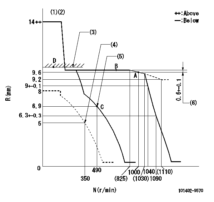
N:Pump speed
R:Rack position (mm)
(1)Target notch: K
(2)Tolerance for racks not indicated: +-0.05mm.
(3)RACK LIMIT
(4)Set idle sub-spring
(5)Main spring setting
(6)Rack difference from N = N1
----------
K=14 N1=700r/min
----------
----------
K=14 N1=700r/min
----------
Speed control lever angle

F:Full speed
I:Idle
(1)Stopper bolt setting
----------
----------
a=9deg+-5deg b=19deg+-5deg
----------
----------
a=9deg+-5deg b=19deg+-5deg
Stop lever angle
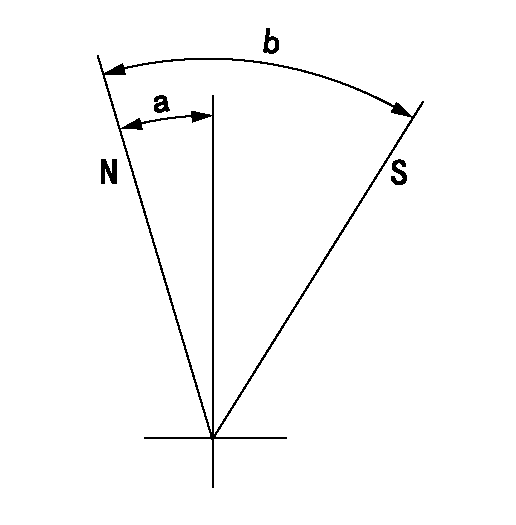
N:Pump normal
S:Stop the pump.
----------
----------
a=7deg+-5deg b=53deg+-5deg
----------
----------
a=7deg+-5deg b=53deg+-5deg
Timing setting

(1)Pump vertical direction
(2)Position of camshaft's key groove at No 1 cylinder's beginning of injection
(3)-
(4)-
----------
----------
a=(60deg)
----------
----------
a=(60deg)
Information:
Keep all parts clean from contaminants. Contaminants put into the system may cause rapid wear and shortened component life.
1. Remove bolts (1) and rocker shaft assembly (2). Remove the O-ring seal from the rear rocker arm support bracket.2. Put identification marks on push rods (3) as to their location in the engine. Remove the push rods. The following steps are for the installation of the rocker shaft assembly and push rods.3. Loosen the adjusting screws (4). This will prevent a bent valve or push rod during installation of the rocker shaft assembly. Install push rods (3). The O-ring seal in the rear support must be installed new each time the bolt is removed from the rear support bracket.4. Install rocker shaft assembly (2).
Make sure the dowels on each end of the rocker shaft assembly are in alignment with the holes in the cylinder head.
5. Put 6V4876 Molykote Lubricant on all of bolts (1) except for bolt (10) that goes through the rear rocker arm support bracket. Install the bolts in the rocker shaft assembly.6. Tighten bolts (1) for the rocker shaft as follows:a. Tighten all the bolts in number sequence to a torque of 155 N m (115 lb ft).b. Tighten all the bolts again in number sequence to a torque of 250 17 N m (185 13 lb ft).c. Last, tighten bolts again in number sequence (hand tighten only to a torque of 250 17 N m (185 13 lb ft).7. The assembled length of springs at both ends of rocker shaft must be 1.50 0.25 mm (.059 .010 in). Remove or install washers behind springs to change the assembled length of the springs.8. Make adjustments until the intake valve clearance is .038 mm (.015 in) and the exhaust valve clearance is 0.64 mm (.025 in). See the topic, Valve Clearance Setting, in Testing And Adjusting. Tighten the locknuts (2) for the adjusting screws (1) to a torque of 29 7 N m (21 5 lb ft).End By:a. install valve cover.Disassemble And Assemble Rocker Shaft
Start By:a. remove rocker shaft and push rods
Keep all parts clean from contaminants. Contaminants put into the system may cause rapid wear and shortened component life.
1. Remove O-ring seal (1). A replacement of the O-ring seal must be made each time the head bolt is removed from the rear support bracket. 2. Remove retainer ring (6), washer (5), spring (4) washer (3) and rocker arm (2). 3. Remove pin from rear support bracket with a hammer and punch. Remove rear support bracket (7).4. Remove remainder of rocker arms, springs, washers and brackets.5. Remove plugs from each end of the shaft if necessary. The following steps are for the assembly of the rocker shaft. 6. Install rocker arms (2), brackets (8), washers (5) and springs (4) on the rocker shaft.7. Install rear support bracket (7). Make sure the hole in rear support bracket is in alignment with the hole in rocker shaft.8. Install pin (9) through
Have questions with 101402-9570?
Group cross 101402-9570 ZEXEL
Yanmar
Mitsubishi-Heav
Yanmar
Mitsubishi-Heav
Yanmar
101402-9570
9 400 614 018
12995451000
INJECTION-PUMP ASSEMBLY
4TNE98
4TNE98