Information injection-pump assembly
BOSCH
9 400 614 016
9400614016
ZEXEL
101402-9550
1014029550
MITSUBISHI-HEAV
3426103010
3426103010

Rating:
Service parts 101402-9550 INJECTION-PUMP ASSEMBLY:
1.
_

5.
AUTOM. ADVANCE MECHANIS
6.
COUPLING PLATE
7.
COUPLING PLATE
8.
_
9.
_
11.
Nozzle and Holder
34361-03011
12.
Open Pre:MPa(Kqf/cm2)
21.6{220}
15.
NOZZLE SET
Cross reference number
BOSCH
9 400 614 016
9400614016
ZEXEL
101402-9550
1014029550
MITSUBISHI-HEAV
3426103010
3426103010
Zexel num
Bosch num
Firm num
Name
Calibration Data:
Adjustment conditions
Test oil
1404 Test oil ISO4113 or {SAEJ967d}
1404 Test oil ISO4113 or {SAEJ967d}
Test oil temperature
degC
40
40
45
Nozzle and nozzle holder
105780-8140
Bosch type code
EF8511/9A
Nozzle
105780-0000
Bosch type code
DN12SD12T
Nozzle holder
105780-2080
Bosch type code
EF8511/9
Opening pressure
MPa
17.2
Opening pressure
kgf/cm2
175
Injection pipe
Outer diameter - inner diameter - length (mm) mm 6-2-600
Outer diameter - inner diameter - length (mm) mm 6-2-600
Overflow valve
131424-5720
Overflow valve opening pressure
kPa
255
221
289
Overflow valve opening pressure
kgf/cm2
2.6
2.25
2.95
Tester oil delivery pressure
kPa
157
157
157
Tester oil delivery pressure
kgf/cm2
1.6
1.6
1.6
Direction of rotation (viewed from drive side)
Right R
Right R
Injection timing adjustment
Direction of rotation (viewed from drive side)
Right R
Right R
Injection order
1-3-4-2
Pre-stroke
mm
3.2
3.15
3.25
Beginning of injection position
Drive side NO.1
Drive side NO.1
Difference between angles 1
Cal 1-3 deg. 90 89.5 90.5
Cal 1-3 deg. 90 89.5 90.5
Difference between angles 2
Cal 1-4 deg. 180 179.5 180.5
Cal 1-4 deg. 180 179.5 180.5
Difference between angles 3
Cyl.1-2 deg. 270 269.5 270.5
Cyl.1-2 deg. 270 269.5 270.5
Injection quantity adjustment
Adjusting point
A
Rack position
8.6
Pump speed
r/min
900
900
900
Average injection quantity
mm3/st.
75
74
76
Max. variation between cylinders
%
0
-2.5
2.5
Basic
*
Fixing the lever
*
Injection quantity adjustment_02
Adjusting point
C
Rack position
6+-0.5
Pump speed
r/min
375
375
375
Average injection quantity
mm3/st.
11.5
10.2
12.8
Max. variation between cylinders
%
0
-14
14
Fixing the rack
*
Injection quantity adjustment_03
Adjusting point
D
Rack position
-
Pump speed
r/min
100
100
100
Average injection quantity
mm3/st.
80
80
85
Fixing the lever
*
Rack limit
*
Test data Ex:
Governor adjustment
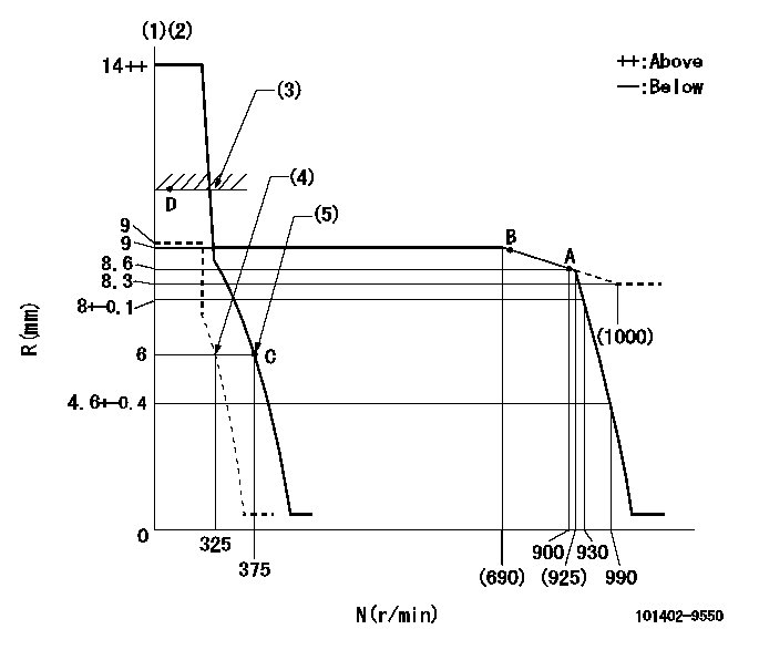
N:Pump speed
R:Rack position (mm)
(1)Target notch: K
(2)Tolerance for racks not indicated: +-0.05mm.
(3)RACK LIMIT
(4)Set idle sub-spring
(5)Main spring setting
----------
K=10
----------
----------
K=10
----------
Speed control lever angle
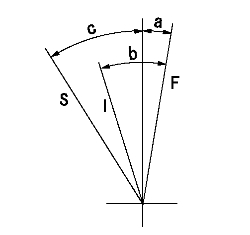
F:Full speed
I:Idle
S:Stop
----------
----------
a=(1deg)+-5deg b=(21deg)+-5deg c=35deg+-3deg
----------
----------
a=(1deg)+-5deg b=(21deg)+-5deg c=35deg+-3deg
Stop lever angle
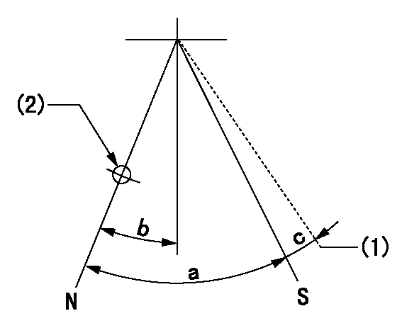
N:Pump normal
S:Stop the pump.
(1)Hold the boss against the stop side
(2)Use the hole at R = aa
----------
aa=60mm
----------
a=53deg+-5deg b=26.5deg+-5deg c=(9deg)
----------
aa=60mm
----------
a=53deg+-5deg b=26.5deg+-5deg c=(9deg)
Timing setting

(1)Pump vertical direction
(2)Position of camshaft's key groove at No 1 cylinder's beginning of injection
(3)-
(4)-
----------
----------
a=(50deg)
----------
----------
a=(50deg)
Information:
2. Remove retainer (4) and two nuts (3). 3. Remove three mounting bolts (6) and bracket (5).Disassemble Turbocharger (Schweitzer S4A)
Start By:a. remove turbocharger 1. Install the turbocharger on tool (A) as shown.2. Put alignment marks on three housings of the turbocharger for correct alignment during assembly. Loosen clamp (2), and remove the clamp and housing (1) from housing assembly (3). 3. Loosen clamp (4), and remove housing assembly (3) from housing (5). 4. Put the cartridge group in position in tool (B) as shown.
When the nut is loosened, do not put a side force on the shaft. This can result in a bent shaft.
5. Use a 5S9566 Sliding T-Wrench and a universal socket (6) to remove the nut that holds the compressor wheel to the wheel assembly.6. Remove compressor wheel (7) and the shims from wheel assembly (8).7. Remove housing assembly (3). 8. Remove ring (9) and backplate (10). 9. Use tool (C), and remove snap ring (11). 10. Remove insert (12) and sleeve (13). 11. Remove ring (14). 12. Remove two screws (15) and deflector (16). 13. Remove ring (18) and bearing assembly (17). 14. Remove sleeve (19) and ring (20). 15. Remove O-ring seal (23). Use tool (D), and remove snap ring (22).16. Remove bearing (21). Remove the snap ring behind the bearing with tool (D). 17. Use tool (D), and remove snap ring (25). Remove bearing (24). Remove the snap ring behind the bearing with tool (D).18. Check all the parts of the turbocharger for damage. If the parts are damaged, use new parts for replacement. See Special Instruction, Form No. SMHS6854, for Turbocharger Reconditioning. Also, see Guidelines For Reusable Parts, Form No. SEBF8018.Assemble Turbocharger (Schweitzer S4A)
1. Make sure that all of the oil passages in the turbocharger cartridge housing are clean and free of dirt and foreign material. Do not put oil on any parts of the turbocharger until after the compressor wheel has been installed. After the turbocharger has been assembled, pour clean engine oil into the oil inlet of the turbocharger.
Make sure that the snap rings that hold bearings (24) and (21) in position in housing assembly (3) are installed with the round edge of the outside diameter toward the bearing.
2. Install the snap ring behind bearing (24) with tool (D). Install bearing (24).3. Use tool (D), and install snap ring (25). 4. Install the snap ring behind bearing (21) with tool (D). Install bearing (21).5. Use tool (D), and install snap ring (22). 6. Put wheel assembly (8) in position on tool (B) as shown. Put backplate (10) in position on the wheel assembly. Put 6V2055 High Vacuum Grease in the groove for seal ring (9) at assembly to one half or more of the depth of the groove all the way around.7. Install ring (9) in the groove in wheel assembly (8). 8. Install housing assembly (3) on wheel assembly (8). 9. Install ring (20) and sleeve (13). 10. Make sure the screen is in place in bearing assembly (17).