Information injection-pump assembly
BOSCH
9 400 614 012
9400614012
ZEXEL
101402-9390
1014029390
YANMAR
12990251400
12990251400
Rating:
Service parts 101402-9390 INJECTION-PUMP ASSEMBLY:
1.
_

5.
AUTOM. ADVANCE MECHANIS
6.
COUPLING PLATE
7.
COUPLING PLATE
8.
_
9.
_
10.
NOZZLE AND HOLDER ASSY
11.
Nozzle and Holder
12.
Open Pre:MPa(Kqf/cm2)
13.
NOZZLE-HOLDER
14.
NOZZLE
15.
NOZZLE SET
Include in #1:
101402-9390
as INJECTION-PUMP ASSEMBLY
Include in #2:
104144-8002
as _
Cross reference number
BOSCH
9 400 614 012
9400614012
ZEXEL
101402-9390
1014029390
YANMAR
12990251400
12990251400
Zexel num
Bosch num
Firm num
Name
101402-9390
9 400 614 012
12990251400 YANMAR
INJECTION-PUMP ASSEMBLY
4TNE98 K
4TNE98 K
Calibration Data:
Adjustment conditions
Test oil
1404 Test oil ISO4113 or {SAEJ967d}
1404 Test oil ISO4113 or {SAEJ967d}
Test oil temperature
degC
40
40
45
Nozzle and nozzle holder
105780-8140
Bosch type code
EF8511/9A
Nozzle
105780-0000
Bosch type code
DN12SD12T
Nozzle holder
105780-2080
Bosch type code
EF8511/9
Opening pressure
MPa
17.2
Opening pressure
kgf/cm2
175
Injection pipe
Outer diameter - inner diameter - length (mm) mm 6-2-600
Outer diameter - inner diameter - length (mm) mm 6-2-600
Overflow valve
131424-1520
Overflow valve opening pressure
kPa
157
123
191
Overflow valve opening pressure
kgf/cm2
1.6
1.25
1.95
Tester oil delivery pressure
kPa
157
157
157
Tester oil delivery pressure
kgf/cm2
1.6
1.6
1.6
Direction of rotation (viewed from drive side)
Right R
Right R
Injection timing adjustment
Direction of rotation (viewed from drive side)
Right R
Right R
Injection order
1-3-4-2
Pre-stroke
mm
3.6
3.55
3.65
Beginning of injection position
Drive side NO.1
Drive side NO.1
Difference between angles 1
Cal 1-3 deg. 90 89.5 90.5
Cal 1-3 deg. 90 89.5 90.5
Difference between angles 2
Cal 1-4 deg. 180 179.5 180.5
Cal 1-4 deg. 180 179.5 180.5
Difference between angles 3
Cyl.1-2 deg. 270 269.5 270.5
Cyl.1-2 deg. 270 269.5 270.5
Injection quantity adjustment
Adjusting point
A
Rack position
10.5
Pump speed
r/min
900
900
900
Average injection quantity
mm3/st.
46.9
45.9
47.9
Max. variation between cylinders
%
0
-2.5
2.5
Basic
*
Fixing the rack
*
Injection quantity adjustment_02
Adjusting point
C
Rack position
8+-0.5
Pump speed
r/min
600
600
600
Average injection quantity
mm3/st.
11.5
10.5
12.5
Max. variation between cylinders
%
0
-15
15
Fixing the rack
*
Injection quantity adjustment_03
Adjusting point
D
Rack position
-
Pump speed
r/min
100
100
100
Average injection quantity
mm3/st.
60
55
65
Fixing the lever
*
Rack limit
*
Test data Ex:
Governor adjustment
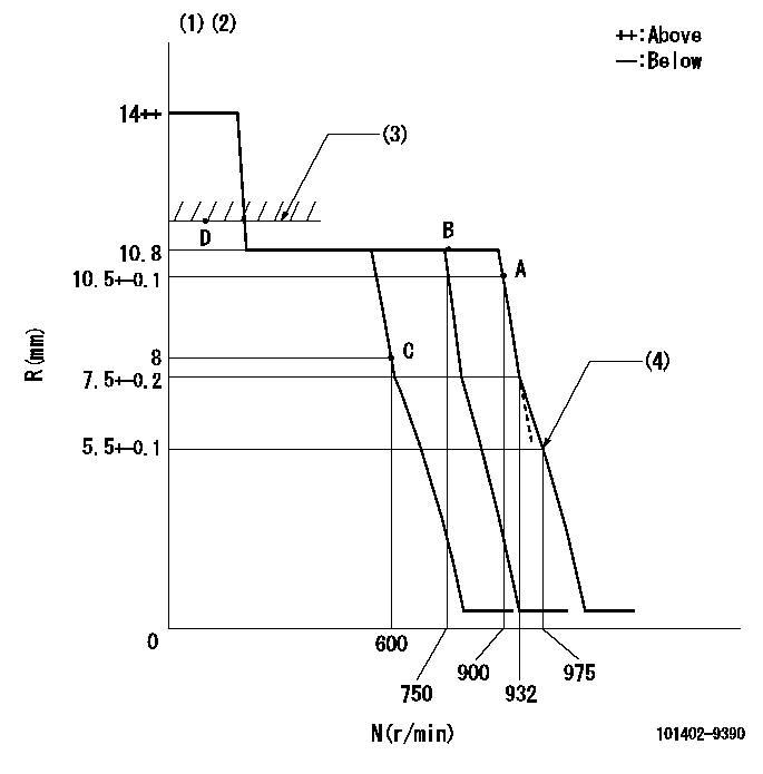
N:Pump speed
R:Rack position (mm)
(1)Target notch: K
(2)Tolerance for racks not indicated: +-0.05mm.
(3)RACK LIMIT
(4)Set idle sub-spring
----------
K=16
----------
----------
K=16
----------
Speed control lever angle
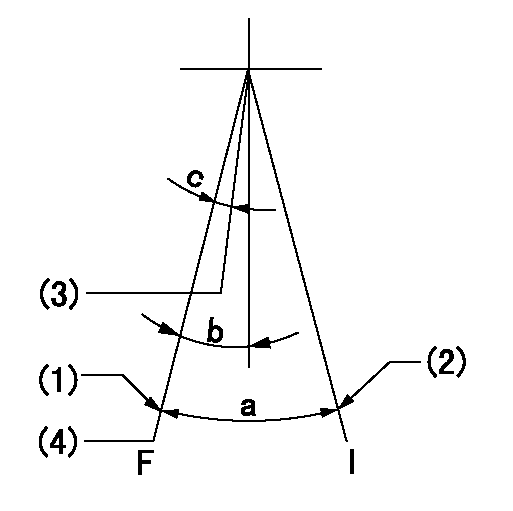
F:Full speed
I:Idle
(1)Stopper bolt setting
(2)Stopper bolt setting
(3)When pump speed set at aa
(4)Set the pump speed at bb.
----------
aa=750r/min bb=900r/min
----------
a=14deg+-5deg b=9deg+-5deg c=6deg+-5deg
----------
aa=750r/min bb=900r/min
----------
a=14deg+-5deg b=9deg+-5deg c=6deg+-5deg
Stop lever angle
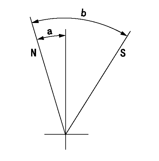
N:Pump normal
S:Stop the pump.
----------
----------
a=7deg+-5deg b=53deg+-5deg
----------
----------
a=7deg+-5deg b=53deg+-5deg
Timing setting

(1)Pump vertical direction
(2)Position of camshaft's key groove at No 1 cylinder's beginning of injection
(3)-
(4)-
----------
----------
a=(60deg)
----------
----------
a=(60deg)
Information:
Install Tooling (E). Tighten Tooling (E) to a torque of 9 1 N m (80 9 lb in).Note: The pump will not function while Tooling (E) is installed. Running the fuel injection pump with the tooling installed will result in pump damage and system contamination.
Illustration 6 g02025176
Disconnect harness assemblies (3).
Remove nut (5) and remove the clamp assembly. Discard the clamp assembly.
Loosen nuts (4) and (7). Remove the fuel line and discard the fuel line.
Disconnect hose assembly (6).
Illustration 7 g02029098
Disconnect tube assemblies (9).
Disconnect hose assemblies (10) and (11).
Remove bolts (8).
Illustration 8 g02029093
Disconnect tube assembly (12).
Illustration 9 g02025262
Remove bolts (13) and remove fuel pump (14).Installing the Fuel Injection Pump
Note: Check the O-ring seals, the gaskets, and the seals for wear or for damage. Replace the components, if necessary.
Illustration 10 g02385860
Service replacement pump
Note: Service replacement pump is shipped pinned with warning tag (Z) installed under pinch bolt (E).
Illustration 11 g02025262
Position fuel pump (14) and install bolts (13).
Illustration 12 g02029093
Connect tube assembly (12).
Illustration 13 g02029098
Install bolts (8).
Connect tube assembly (9) and connect both hose assemblies (10) and (11).
Illustration 14 g02025176Note: During installation, make sure that the fuel line caps remain in position until the fuel line is positioned near the corresponding ports in order to prevent contamination. Ensure that the areas around the rail and fuel lines are thoroughly clean before continuing this procedure. If any parts are worn or damaged, use new parts for replacement. Cleanliness is an important factor. Ensure that no debris gets introduced into the fuel system during the installation procedure. If any parts are worn or damaged, use new parts for replacement.
Connect harness assemblies (3).
Install a new fuel line. Hand tighten nuts (4) and (7).
Position the clamp assembly and install nut (5). Hand tighten the nut. Failure to place the grommet correctly on the fuel line could result in a failed fuel line.Note: Ensure that the fuel lines are centered in the nuts prior to tightening. Do not use excessive force or bending in order to assemble the fuel lines.
Tighten nut (4) at the fuel rail to a torque of 27 3 N m (239 27 lb in).
Tighten nut (7) to a torque of 27 3 N m (239 27 lb in).
Tighten nut (5) to a torque of 12 3 N m (105 27 lb in).
Illustration 15 g02351995
Remove Tooling (E) and warning tag (Z).Note: The pump will not function while Tooling (E) is installed. Running the fuel injection pump with the tooling installed will result in pump damage and system contamination.
Illustration 16 g02351981
Install O-ring seal (2) and plug (1). Tighten the plug to a torque of 9 1 N m (80 9 lb in).
Illustration 17 g02112896
Remove all tooling. Reinstall plug (X) into the timing hole that is located in the flywheel housing.
Connect Caterpillar Electronic Technician (ET). Perform a “Fuel System Functional Test ”and a “Fuel System Verification Test”.
Have questions with 101402-9390?
Group cross 101402-9390 ZEXEL
Mitsubishi-Heav
Mitsubishi-Heav
Mitsubishi-Heav
Mitsubishi-Heav
Yanmar
Yanmar
Yanmar
Yanmar
101402-9390
9 400 614 012
12990251400
INJECTION-PUMP ASSEMBLY
4TNE98
4TNE98