Information injection-pump assembly
BOSCH
9 400 610 489
9400610489
ZEXEL
101402-9090
1014029090
YANMAR
12745051010
12745051010
Rating:
Service parts 101402-9090 INJECTION-PUMP ASSEMBLY:
1.
_
6.
COUPLING PLATE
7.
COUPLING PLATE
8.
_
9.
_
11.
Nozzle and Holder
12.
Open Pre:MPa(Kqf/cm2)
19.6{200}
15.
NOZZLE SET
Cross reference number
BOSCH
9 400 610 489
9400610489
ZEXEL
101402-9090
1014029090
YANMAR
12745051010
12745051010
Zexel num
Bosch num
Firm num
Name
101402-9090
9 400 610 489
12745051010 YANMAR
INJECTION-PUMP ASSEMBLY
4CHLTN K 14BC INJECTION PUMP ASSY PE4A,5A, PE
4CHLTN K 14BC INJECTION PUMP ASSY PE4A,5A, PE
Calibration Data:
Adjustment conditions
Test oil
1404 Test oil ISO4113 or {SAEJ967d}
1404 Test oil ISO4113 or {SAEJ967d}
Test oil temperature
degC
40
40
45
Nozzle and nozzle holder
105780-8140
Bosch type code
EF8511/9A
Nozzle
105780-0000
Bosch type code
DN12SD12T
Nozzle holder
105780-2080
Bosch type code
EF8511/9
Opening pressure
MPa
17.2
Opening pressure
kgf/cm2
175
Injection pipe
Outer diameter - inner diameter - length (mm) mm 6-2-600
Outer diameter - inner diameter - length (mm) mm 6-2-600
Overflow valve
132424-0620
Overflow valve opening pressure
kPa
157
123
191
Overflow valve opening pressure
kgf/cm2
1.6
1.25
1.95
Tester oil delivery pressure
kPa
157
157
157
Tester oil delivery pressure
kgf/cm2
1.6
1.6
1.6
Direction of rotation (viewed from drive side)
Right R
Right R
Injection timing adjustment
Direction of rotation (viewed from drive side)
Right R
Right R
Injection order
1-2-4-3
Pre-stroke
mm
3
2.95
3.05
Beginning of injection position
Drive side NO.1
Drive side NO.1
Difference between angles 1
Cyl.1-2 deg. 90 89.5 90.5
Cyl.1-2 deg. 90 89.5 90.5
Difference between angles 2
Cal 1-4 deg. 180 179.5 180.5
Cal 1-4 deg. 180 179.5 180.5
Difference between angles 3
Cal 1-3 deg. 270 269.5 270.5
Cal 1-3 deg. 270 269.5 270.5
Injection quantity adjustment
Adjusting point
A
Rack position
8.5
Pump speed
r/min
900
900
900
Each cylinder's injection qty
mm3/st.
40.8
39.8
41.8
Basic
*
Fixing the rack
*
Injection quantity adjustment_02
Adjusting point
C
Rack position
6+-0.5
Pump speed
r/min
300
300
300
Each cylinder's injection qty
mm3/st.
8.7
7.7
9.7
Fixing the rack
*
Test data Ex:
Governor adjustment
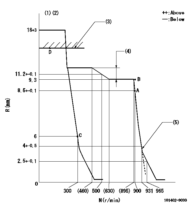
N:Pump speed
R:Rack position (mm)
(1)Target notch: K
(2)Tolerance for racks not indicated: +-0.05mm.
(3)RACK LIMIT; RAL(Shim 0)
(4)Torque control stroke: L1 (N = N1 and N = N2 rack difference).
(5)Set idle sub-spring
----------
K=6 RAL=15.4mm L1=2.4+-0.2mm N1=850r/min N2=400r/min
----------
----------
K=6 RAL=15.4mm L1=2.4+-0.2mm N1=850r/min N2=400r/min
----------
Speed control lever angle
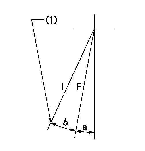
F:Full speed
I:Idle
(1)Stopper bolt setting
----------
----------
a=0deg+-5deg b=18deg+-5deg
----------
----------
a=0deg+-5deg b=18deg+-5deg
Stop lever angle
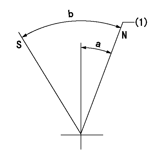
N:Pump normal
S:Stop the pump.
(1)Normal
----------
----------
a=20deg+-5deg b=53deg+-5deg
----------
----------
a=20deg+-5deg b=53deg+-5deg
Information:
1. Remove oil supply tube (1) and suction bell and tube (2). 2. Remove bolts (3) that hold the oil pump to the cylinder block, and remove oil pump (4).Install Oil Pump
1. Put oil pump (1) in position on the cylinder block. Install the bolts that hold the oil pump to the cylinder block. 2. Put clean engine oil on the O-ring seals of the tubes.3. Install oil supply tube (2) and suction bell and tube (3).END BY:a. install oil panDisassemble Oil Pump
START BY:a. remove oil pump1. Remove the bolt and washer that hold the gear on the shaft. 2. Use tooling (A), and remove drive gear (1) from the shaft. Remove the key from the shaft. 3. Remove retainer (3) for the bypass valve.4. Remove the spring and bypass valve.5. Remove cover (2) from the pump body. 6. Use tooling (B), and remove the bearings from the cover. 7. Remove gears (5) from pump body (4).8. Use tooling (B), and remove the bearings from pump body (4).Assemble Oil Pump
1. Use tooling (A) to install the bearings in the pump body. Install the bearings so the joint in the bearings is 30° 15° from the center line of the oil pump outlet passage (2). 2. Install idler gear (1) and drive gear (3) in the oil pump body. Put clean engine oil on the bearings and the gears. 3. Use tooling (A), and install the bearings in cover (4). Install the bearings so the joint in the bearings is 30° 15° from the center line of the bearing bores toward oil pump outlet passage (2).4. Install bypass valve (5), spring (6) and the retainer.5. Install the key on the shaft. 6. Install gear (7) on the shaft. Install the washer and bolt that hold the gear on the shaft. Be sure the pump turns freely after assembly.END BY:a. install oil pump
Have questions with 101402-9090?
Group cross 101402-9090 ZEXEL
Yanmar
101402-9090
9 400 610 489
12745051010
INJECTION-PUMP ASSEMBLY
4CHLTN
4CHLTN