Information injection-pump assembly
ZEXEL
101402-9080
1014029080
YANMAR
12643051010
12643051010
Rating:
Service parts 101402-9080 INJECTION-PUMP ASSEMBLY:
1.
_
2.
FUEL INJECTION PUMP
6.
COUPLING PLATE
7.
COUPLING PLATE
8.
_
9.
_
10.
NOZZLE AND HOLDER ASSY
11.
Nozzle and Holder
12.
Open Pre:MPa(Kqf/cm2)
13.
NOZZLE-HOLDER
14.
NOZZLE
15.
NOZZLE SET
Cross reference number
ZEXEL
101402-9080
1014029080
YANMAR
12643051010
12643051010
Zexel num
Bosch num
Firm num
Name
Calibration Data:
Adjustment conditions
Test oil
1404 Test oil ISO4113 or {SAEJ967d}
1404 Test oil ISO4113 or {SAEJ967d}
Test oil temperature
degC
40
40
45
Nozzle and nozzle holder
105780-8140
Bosch type code
EF8511/9A
Nozzle
105780-0000
Bosch type code
DN12SD12T
Nozzle holder
105780-2080
Bosch type code
EF8511/9
Opening pressure
MPa
17.2
Opening pressure
kgf/cm2
175
Injection pipe
Outer diameter - inner diameter - length (mm) mm 6-2-600
Outer diameter - inner diameter - length (mm) mm 6-2-600
Tester oil delivery pressure
kPa
157
157
157
Tester oil delivery pressure
kgf/cm2
1.6
1.6
1.6
Direction of rotation (viewed from drive side)
Right R
Right R
Injection timing adjustment
Direction of rotation (viewed from drive side)
Right R
Right R
Injection order
1-2-4-3
Pre-stroke
mm
3.8
3.75
3.85
Beginning of injection position
Drive side NO.1
Drive side NO.1
Difference between angles 1
Cyl.1-2 deg. 90 89.5 90.5
Cyl.1-2 deg. 90 89.5 90.5
Difference between angles 2
Cal 1-4 deg. 180 179.5 180.5
Cal 1-4 deg. 180 179.5 180.5
Difference between angles 3
Cal 1-3 deg. 270 269.5 270.5
Cal 1-3 deg. 270 269.5 270.5
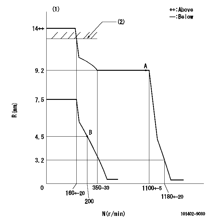
Injection quantity adjustment
Adjusting point
A
Rack position
9.2
Pump speed
r/min
1100
1100
1100
Each cylinder's injection qty
mm3/st.
128.2
126.3
130.1
Basic
*
Fixing the rack
*
Injection quantity adjustment_02
Adjusting point
B
Rack position
4.5+-0.5
Pump speed
r/min
200
200
200
Each cylinder's injection qty
mm3/st.
16
15
17
Fixing the rack
*
Test data Ex:
Governor adjustment
N:Pump speed
R:Rack position (mm)
(1)Target notch: K
(2)RACK LIMIT: RAL
----------
K=4 RAL=11.6+0.2mm
----------
----------
K=4 RAL=11.6+0.2mm
----------
Speed control lever angle
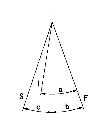
F:Full speed
I:Idle
S:Stop
----------
----------
a=35deg+-5deg b=10deg+-5deg c=32deg+-3deg
----------
----------
a=35deg+-5deg b=10deg+-5deg c=32deg+-3deg
Stop lever angle

N:Pump normal
S:Stop the pump.
----------
----------
a=(20deg) b=(53deg)
----------
----------
a=(20deg) b=(53deg)
Information:
START BY:a. remove fuel filter and base1. Drain the coolant from the engine.
Do not disconnect the air line from the compressor governor until the air pressure is zero.
2. Loosen the bleed valve and release the air pressure in the air tank. 3. Disconnect air compressor line (1) and fuel ratio control line (2) from the aftercooler housing. 4. Remove four turbocharger tube adapter to aftercooler housing bolts (3), nuts and cover. Loosen turbocharger compressor housing clamp (4), and rotate turbocharger tube (5) out of the way of the aftercooler housing. 5. Fasten tooling (A) and a hoist to aftercooler housing (6). Remove bolts (7) that hold the aftercooler housing to the cylinder head assembly. Remove the aftercooler housing from the engine. The weight is 36 kg (80 lb.).Install Aftercooler Housing
1. Install new O-ring seals (1) on the aftercooler water inlet and outlet pipes. Lubricate the O-ring seals with clean engine oil. Put new gaskets in position on the cylinder head assembly.2. Fasten tooling (A) and a hoist to aftercooler housing (2), and put the aftercooler housing in position on the water pipes and cylinder head assembly.3. Put 9S3263 Thread Lock on the threads of the bolts, and install the bolts that hold the aftercooler housing to the cylinder head assembly. 4. Rotate turbocharger tube (3) into position. Place a gasket between the aftercooler housing and adapter, and install four bolts and nuts that hold it. Tighten turbocharger clamp nut (4) to a torque of 18 3 N m (13 2 lb.ft.). Lightly hit all around the clamp with a soft faced hammer, and tighten the clamp nut again to the same torque value. 5. Connect air compressor line (5) and fuel ratio control line (6).6. Fill engine with coolant to the correct level. See the Maintenance Guide.END BY:a. install fuel filter and base