Information injection-pump assembly
ZEXEL
101402-9061
1014029061
YANMAR
12741251010
12741251010
Rating:
Service parts 101402-9061 INJECTION-PUMP ASSEMBLY:
1.
_
2.
FUEL INJECTION PUMP
6.
COUPLING PLATE
7.
COUPLING PLATE
8.
_
9.
_
10.
NOZZLE AND HOLDER ASSY
11.
Nozzle and Holder
12.
Open Pre:MPa(Kqf/cm2)
13.
NOZZLE-HOLDER
14.
NOZZLE
15.
NOZZLE SET
Cross reference number
ZEXEL
101402-9061
1014029061
YANMAR
12741251010
12741251010
Zexel num
Bosch num
Firm num
Name
Calibration Data:
Adjustment conditions
Test oil
1404 Test oil ISO4113 or {SAEJ967d}
1404 Test oil ISO4113 or {SAEJ967d}
Test oil temperature
degC
40
40
45
Nozzle and nozzle holder
105780-8140
Bosch type code
EF8511/9A
Nozzle
105780-0000
Bosch type code
DN12SD12T
Nozzle holder
105780-2080
Bosch type code
EF8511/9
Opening pressure
MPa
17.2
Opening pressure
kgf/cm2
175
Injection pipe
Outer diameter - inner diameter - length (mm) mm 6-2-600
Outer diameter - inner diameter - length (mm) mm 6-2-600
Overflow valve
131424-0220
Overflow valve opening pressure
kPa
157
123
191
Overflow valve opening pressure
kgf/cm2
1.6
1.25
1.95
Tester oil delivery pressure
kPa
157
157
157
Tester oil delivery pressure
kgf/cm2
1.6
1.6
1.6
Direction of rotation (viewed from drive side)
Right R
Right R
Injection timing adjustment
Direction of rotation (viewed from drive side)
Right R
Right R
Injection order
1-2-4-3
Pre-stroke
mm
3.8
3.75
3.85
Beginning of injection position
Drive side NO.1
Drive side NO.1
Difference between angles 1
Cyl.1-2 deg. 90 89.5 90.5
Cyl.1-2 deg. 90 89.5 90.5
Difference between angles 2
Cal 1-4 deg. 180 179.5 180.5
Cal 1-4 deg. 180 179.5 180.5
Difference between angles 3
Cal 1-3 deg. 270 269.5 270.5
Cal 1-3 deg. 270 269.5 270.5
Injection quantity adjustment
Adjusting point
A
Rack position
9.1
Pump speed
r/min
1300
1300
1300
Each cylinder's injection qty
mm3/st.
85.3
83.6
87
Basic
*
Fixing the rack
*
Injection quantity adjustment_02
Adjusting point
B
Rack position
5+-0.5
Pump speed
r/min
200
200
200
Each cylinder's injection qty
mm3/st.
11.2
9.2
13.2
Fixing the rack
*
Injection quantity adjustment_03
Adjusting point
C
Rack position
13.4+-0.
5
Pump speed
r/min
100
100
100
Each cylinder's injection qty
mm3/st.
136
136
166
Fixing the lever
*
Injection quantity adjustment_04
Adjusting point
D
Rack position
4
Pump speed
r/min
1300
1300
1300
Each cylinder's injection qty
mm3/st.
7.1
5.3
8.9
Fixing the rack
*
Test data Ex:
Governor adjustment
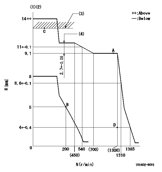
N:Pump speed
R:Rack position (mm)
(1)Target notch: K
(2)Tolerance for racks not indicated: +-0.05mm.
(3)RACK LIMIT
(4)Rack difference between N = N1 and N = N2
----------
K=8 N1=1300r/min N2=350r/min
----------
----------
K=8 N1=1300r/min N2=350r/min
----------
Speed control lever angle
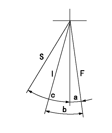
F:Full speed
I:Idle
S:Stop
----------
----------
a=12deg+-5deg b=29deg+-5deg c=32deg+-3deg
----------
----------
a=12deg+-5deg b=29deg+-5deg c=32deg+-3deg
Stop lever angle
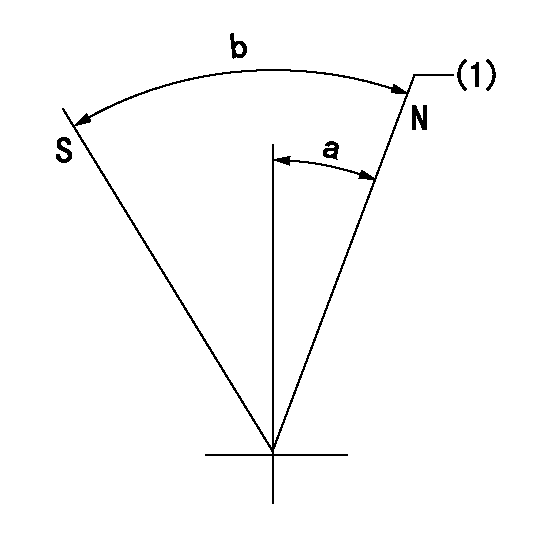
N:Pump normal
S:Stop the pump.
(1)Normal
----------
----------
a=20deg+-5deg b=53deg+-5deg
----------
----------
a=20deg+-5deg b=53deg+-5deg
Information:
START BY:a. remove valve coversb. remove rocker shaft assemblies and pushrodsc. remove fuel injection nozzles (earlier)
Be sure that the piston is at Top Center so that the valves will be held in position when the springs are removed.
1. Remove the valve cover bases.2. Remove the valve stem locks with tooling (A) using the following procedure: a. Install adapter plate (1) with two OS1618 (5/16-18 x 1 in.) bolts.b. Install stud (2) and nut (3). Tighten the nut. c. Install plate (4), washer (5) and nut (6). Tighten the nut until the locks are free.d. Remove locks (7), and remove the nut, washer and plate from the stud. Remove the stud and adapter plate from the fuel injection nozzle adapter. 3. Remove rotocoil (8), spring (9) and washer (10). 4. Use tool (B) to remove fuel injection nozzle adapter (11) from the cylinder head assembly. 5. Remove washers (12) and seals (13) from adapters (11).Install Fuel Injection Nozzle Adapters (Earlier)
1. Inspect seals (3) for damage or wear, and make a replacement if necessary.2. Install washers (1) and seals (3) on adapters (2).3. Put liquid soap in the bores of the cylinder head and on the seals of the fuel injection nozzle adapters.4. Put 5P3931 Anti-Seize Compound on the threads of adapter (2), and install the adapters in the cylinder head assembly. 5. Use tool (A), and tighten the adapters to a torque of 205 14 N m (150 10 lb.ft.). 6. Install washers (6), springs (5) and rotocoils (4). 7. Use tool (B), and compress the springs until locks (7) can be installed. Install locks (7) on the valve stems, and remove tool (B).8. Install the valve cover base. Tighten the valve cover base mounting bolts to a torque of 14 3 N m (10 2 lb.ft.).END BY:a. install fuel injection nozzles (earlier)b. install rocker shaft assemblies and push rodsc. install valve covers