Information injection-pump assembly
BOSCH
9 400 613 993
9400613993
ZEXEL
101402-9040
1014029040
YANMAR
12742051012
12742051012
Rating:
Service parts 101402-9040 INJECTION-PUMP ASSEMBLY:
1.
_
6.
COUPLING PLATE
7.
COUPLING PLATE
8.
_
9.
_
10.
NOZZLE AND HOLDER ASSY
11.
Nozzle and Holder
12.
Open Pre:MPa(Kqf/cm2)
13.
NOZZLE-HOLDER
14.
NOZZLE
15.
NOZZLE SET
Cross reference number
BOSCH
9 400 613 993
9400613993
ZEXEL
101402-9040
1014029040
YANMAR
12742051012
12742051012
Zexel num
Bosch num
Firm num
Name
101402-9040
9 400 613 993
12742051012 YANMAR
INJECTION-PUMP ASSEMBLY
4H25 K 14BC INJECTION PUMP ASSY PE4A,5A, PE
4H25 K 14BC INJECTION PUMP ASSY PE4A,5A, PE
Calibration Data:
Adjustment conditions
Test oil
1404 Test oil ISO4113 or {SAEJ967d}
1404 Test oil ISO4113 or {SAEJ967d}
Test oil temperature
degC
40
40
45
Nozzle and nozzle holder
105780-8140
Bosch type code
EF8511/9A
Nozzle
105780-0000
Bosch type code
DN12SD12T
Nozzle holder
105780-2080
Bosch type code
EF8511/9
Opening pressure
MPa
17.2
Opening pressure
kgf/cm2
175
Injection pipe
Outer diameter - inner diameter - length (mm) mm 6-2-600
Outer diameter - inner diameter - length (mm) mm 6-2-600
Tester oil delivery pressure
kPa
157
157
157
Tester oil delivery pressure
kgf/cm2
1.6
1.6
1.6
Direction of rotation (viewed from drive side)
Right R
Right R
Injection timing adjustment
Direction of rotation (viewed from drive side)
Right R
Right R
Injection order
1-2-4-3
Pre-stroke
mm
3
2.95
3.05
Beginning of injection position
Drive side NO.1
Drive side NO.1
Difference between angles 1
Cyl.1-2 deg. 90 89.5 90.5
Cyl.1-2 deg. 90 89.5 90.5
Difference between angles 2
Cal 1-4 deg. 180 179.5 180.5
Cal 1-4 deg. 180 179.5 180.5
Difference between angles 3
Cal 1-3 deg. 270 269.5 270.5
Cal 1-3 deg. 270 269.5 270.5
Injection quantity adjustment
Adjusting point
A
Rack position
9.8
Pump speed
r/min
1400
1400
1400
Each cylinder's injection qty
mm3/st.
66
64.3
67.7
Basic
*
Fixing the rack
*
Injection quantity adjustment_02
Adjusting point
B
Rack position
6+-0.5
Pump speed
r/min
200
200
200
Each cylinder's injection qty
mm3/st.
13.4
12.4
14.4
Fixing the rack
*
Injection quantity adjustment_03
Adjusting point
C
Rack position
10.9+-0.
5
Pump speed
r/min
100
100
100
Each cylinder's injection qty
mm3/st.
74
74
102
Fixing the lever
*
Rack limit
*
Test data Ex:
Governor adjustment
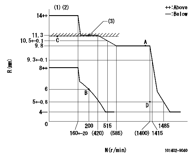
N:Pump speed
R:Rack position (mm)
(1)Target notch: K
(2)Tolerance for racks not indicated: +-0.05mm.
(3)RACK LIMIT: RAL
----------
K=3 RAL=10.9+-0.5mm
----------
----------
K=3 RAL=10.9+-0.5mm
----------
Speed control lever angle
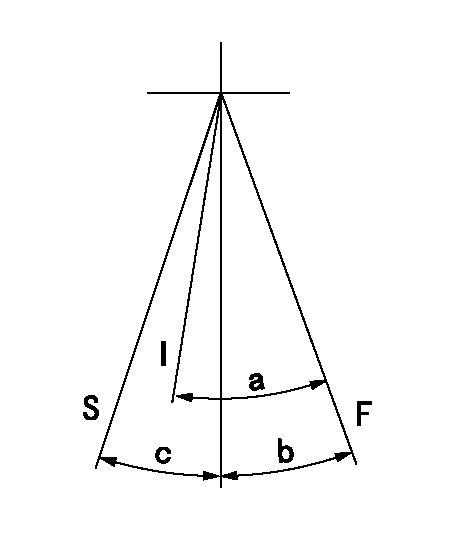
F:Full speed
I:Idle
S:Stop
----------
----------
a=30deg+-5deg b=12deg+-5deg c=32deg+-3deg
----------
----------
a=30deg+-5deg b=12deg+-5deg c=32deg+-3deg
Stop lever angle
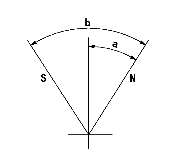
N:Pump normal
S:Stop the pump.
----------
----------
a=20deg+-5deg b=53deg+-5deg
----------
----------
a=20deg+-5deg b=53deg+-5deg
Information:
START BY:a. remove valve covers
Do not let the tops of the fuel nozzles turn when the fuel lines are loosened. The nozzles will be damaged if the top of the nozzles turns in the body.
1. Loosen the fuel injection line nut at the nozzle end with tool (A) and a 5P328 crowfoot wrench (7/8").2. Loosen the fuel line nut at the fuel injection line adapter with tool (B). Remove inner fuel injection lines (1). Install caps and plugs on all fuel line openings to keep dirt out of the fuel system. If necessary, use tooling (D) to turn the engine so the valves do not make contact with the pistons when the valves are opened with tool (C) to remove the push rods.3. Put compression on the valve springs with tool (C), and remove push rods (2). Put identification marks on the push rods as to their location in the engine.4. Push the push rod end of the rocker arms down. 5. Remove the intake valve lifter with tooling (E) as follows:a. Install 5P2685 Nut (3) and 5P6601 Collet (4) on 5P2408 Outer Handle Assembly (5).b. Install 5P6599 Inner Handle Assembly (6) in 5P2408 Outer Handle Assembly (5). c. Install tooling (E) in the intake valve lifter. Hold the 5P2408 Outer Handle Assembly, and tighten the 5P6599 Inner Handle Assembly until the 5P6601 Collet is tight against the inside of the intake valve lifter. d. Remove intake valve lifters (7) from the cylinder block with tooling (E). Put identification marks on the lifters as to their location in the engine. 6. Remove the exhaust valve lifters with tooling (E) as follows:a. Install 5P2685 Nut (3) and 5P6601 Collet (4) on 5P2408 Outer Handle Assembly (5). The opening in the cylinder head assembly for the intake valve lifter is larger than the opening in the exhaust valve lifter side. The tooling and each valve lifter must be installed and removed from the intake valve lifter side.b. Install the outer handle assembly in the intake valve lifter side of the cylinder head assembly. Slide the flat area of 5P2408 Outer Handle Assembly (5) through the head casting, and install the 5P6601 Collet in the exhaust valve lifters. c. Install 5P6599 Inner Handle Assembly (6) in 5P2408 Outer Handle Assembly (5). Hold the 5P2408 Handle Assembly, and tighten the 5P6599 Handle Assembly until the 5P6601 Collet is tight against the inside of the exhaust valve lifter.d. Pull the exhaust valve lifter up until the spring on the exhaust valve lifter is free from the cylinder block.e. Remove the 5P6599 Inner Handle Assembly. Slide the 5P2408 Outer Handle Assembly through the head casting, and remove it from the intake valve lifter side of the cylinder head. f. Use a magnet, and remove exhaust valve lifters (8) from the intake valve lifter side of the cylinder head assembly. Put identification marks on the lifters as to their location in the engine.7. Remove the guide springs from the lifters.Install Valve Lifters
Steps 1 and 2
Have questions with 101402-9040?
Group cross 101402-9040 ZEXEL
Yanmar
101402-9040
9 400 613 993
12742051012
INJECTION-PUMP ASSEMBLY
4H25
4H25