Information injection-pump assembly
BOSCH
9 400 611 936
9400611936
ZEXEL
101402-9000
1014029000
YANMAR
12645051010
12645051010
Rating:
Service parts 101402-9000 INJECTION-PUMP ASSEMBLY:
1.
_
5.
AUTOM. ADVANCE MECHANIS
6.
COUPLING PLATE
7.
COUPLING PLATE
8.
_
9.
_
10.
NOZZLE AND HOLDER ASSY
11.
Nozzle and Holder
12.
Open Pre:MPa(Kqf/cm2)
13.
NOZZLE-HOLDER
14.
NOZZLE
15.
NOZZLE SET
Cross reference number
BOSCH
9 400 611 936
9400611936
ZEXEL
101402-9000
1014029000
YANMAR
12645051010
12645051010
Zexel num
Bosch num
Firm num
Name
101402-9000
9 400 611 936
12645051010 YANMAR
INJECTION-PUMP ASSEMBLY
4HAL K 14BC INJECTION PUMP ASSY PE4A,5A, PE
4HAL K 14BC INJECTION PUMP ASSY PE4A,5A, PE
Calibration Data:
Adjustment conditions
Test oil
1404 Test oil ISO4113 or {SAEJ967d}
1404 Test oil ISO4113 or {SAEJ967d}
Test oil temperature
degC
40
40
45
Nozzle and nozzle holder
105780-8140
Bosch type code
EF8511/9A
Nozzle
105780-0000
Bosch type code
DN12SD12T
Nozzle holder
105780-2080
Bosch type code
EF8511/9
Opening pressure
MPa
17.2
Opening pressure
kgf/cm2
175
Injection pipe
Outer diameter - inner diameter - length (mm) mm 6-2-600
Outer diameter - inner diameter - length (mm) mm 6-2-600
Overflow valve
131424-1520
Overflow valve opening pressure
kPa
157
123
191
Overflow valve opening pressure
kgf/cm2
1.6
1.25
1.95
Tester oil delivery pressure
kPa
157
157
157
Tester oil delivery pressure
kgf/cm2
1.6
1.6
1.6
Direction of rotation (viewed from drive side)
Right R
Right R
Injection timing adjustment
Direction of rotation (viewed from drive side)
Right R
Right R
Injection order
1-2-4-3
Pre-stroke
mm
2.7
2.65
2.75
Beginning of injection position
Drive side NO.1
Drive side NO.1
Difference between angles 1
Cyl.1-2 deg. 90 89.5 90.5
Cyl.1-2 deg. 90 89.5 90.5
Difference between angles 2
Cal 1-4 deg. 180 179.5 180.5
Cal 1-4 deg. 180 179.5 180.5
Difference between angles 3
Cal 1-3 deg. 270 269.5 270.5
Cal 1-3 deg. 270 269.5 270.5
Injection quantity adjustment
Adjusting point
A
Rack position
12.8
Pump speed
r/min
900
900
900
Each cylinder's injection qty
mm3/st.
121
118.6
123.4
Basic
*
Fixing the rack
*
Injection quantity adjustment_02
Adjusting point
B
Rack position
7.5+-0.5
Pump speed
r/min
250
250
250
Each cylinder's injection qty
mm3/st.
15
13.5
16.5
Fixing the rack
*
Test data Ex:
Governor adjustment
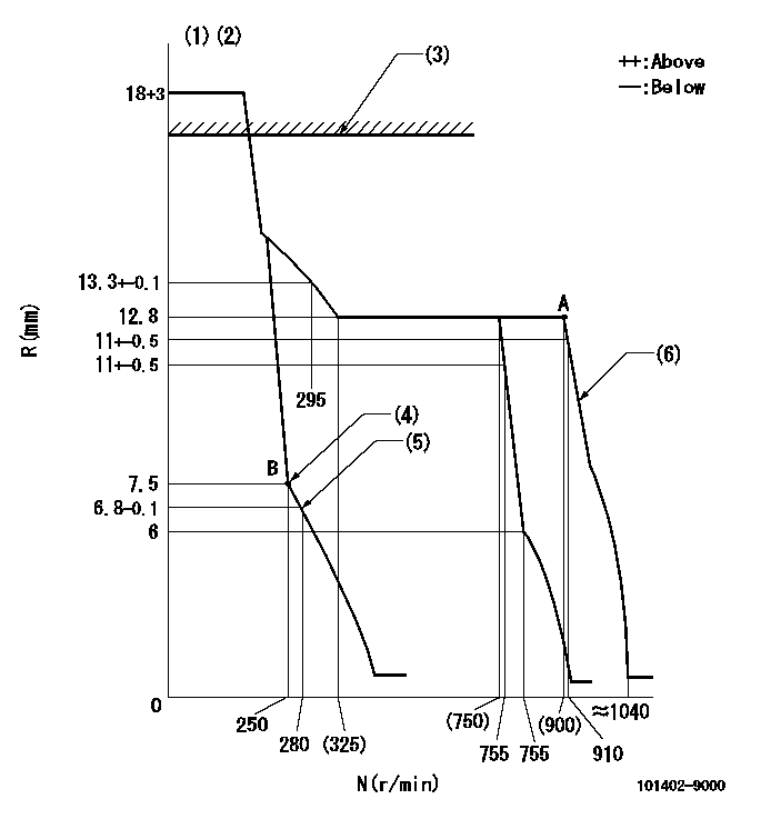
N:Pump speed
R:Rack position (mm)
(1)Target notch: K
(2)Tolerance for racks not indicated: +-0.05mm.
(3)At rack cap installation: R1 or more
(4)Main spring setting
(5)Set idle sub-spring
(6)Full speed setting
----------
K=7 R1=18mm
----------
----------
K=7 R1=18mm
----------
Speed control lever angle
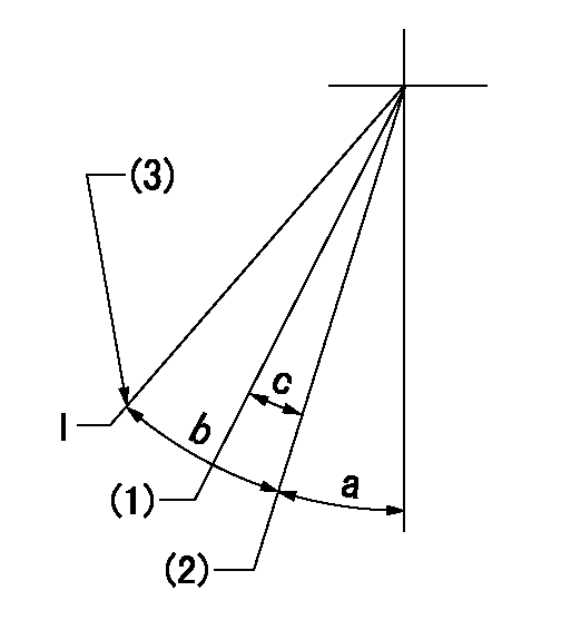
I:Idle
(1)Set the pump speed at aa
(2)Set the pump speed at bb.
(3)Stopper bolt setting
----------
aa=755r/min bb=910r/min
----------
a=17deg+-5deg b=32deg+-5deg c=7deg+-3deg
----------
aa=755r/min bb=910r/min
----------
a=17deg+-5deg b=32deg+-5deg c=7deg+-3deg
Stop lever angle
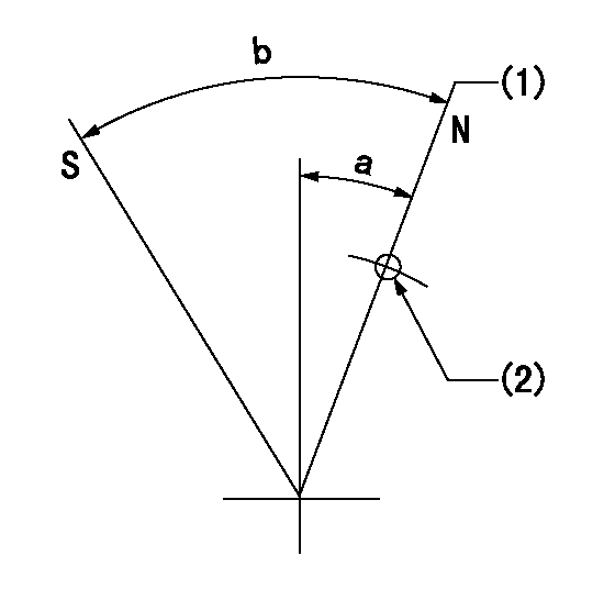
N:Pump normal
S:Stop the pump.
(1)Normal
(2)Use the hole at R = aa
----------
aa=40mm
----------
a=20deg+-5deg b=53deg+-5deg
----------
aa=40mm
----------
a=20deg+-5deg b=53deg+-5deg
Information:
4. Put clean engine oil on the O-ring seal, and assemble elbow (4) to drain tube (5).5. Put the gaskets in position on the block and on the turbocharger, and install the drain tube assembly. 6. Put a gasket in position between oil supply tube (6) and the turbocharger. Install oil supply tube (6).Disassemble Turbocharger (TV72 & TV78)
START BY:a. remove turbocharger (TV72 & TV78) 1. Install the turbocharger in tool group (A). Put alignment marks on the three housings of the turbocharger for correct installation and alignment at assembly. Remove "V" clamp (2) and compressor housing (1). 2. Remove "V" clamp (3). Remove cartridge housing (5) from turbine housing (4).
When the nut is loosened, do not put a side force on the shaft. This can result in a bent shaft.
3. Install tool (C) in tool (B), and put the cartridge assembly in tool (C) as shown. Use tool (D) to remove the nut that holds compressor wheel (6). 4. Put the cartridge assembly in tool (E), and use a press (if necessary) to remove compressor wheel (6) from the turbine wheel and shaft assembly. Do not let the turbine wheel and shaft assembly fall during removal of the compressor wheel from the turbine wheel and shaft. 5. Remove seal ring (7) and shroud (8) from turbine wheel and shaft assembly (9). 6. Bend the tabs of the locks from bolts (10), and remove the bolts and locks.7. Remove backplate assembly (11) from the cartridge housing. 8. Remove spacer (12) from backplate assembly (11). Remove seal rings (13) from spacer (12). 9. Remove collar (14), thrust bearing (15) and O-ring seal (16) from the cartridge housing. 10. Remove top bearing (17) and the washer from the cartridge housing. Put a long dye mark on the top face of bearing (17).11. Use tool (F), and remove the two rings that hold the top and bottom bearings in position. Remove the bottom bearing and washer. Put a short dye mark on the bearing. The dye marks are used for identification of the bearings when they are installed.12. Use tool (F), and remove the last ring that holds the bottom bearing in position from the cartridge housing.13. Check all the parts of the turbocharger for damage. If the parts are damaged, use new parts for replacement. See Special Instruction Form No. SMHS6854 for Turbocharger Reconditioning. Also see Guidelines For Reuseable Parts, Form No. SEBF8018.Assemble Turbocharger (TV72 & TV78)
1. Make sure that all of the oil passages in the turbocharger cartridge housing are clean and free of dirt and foreign material.2. Put clean engine oil on all parts of the cartridge assembly.
Rings (1), (4) and (5) must be installed with the round edge of the outside diameter of the rings toward the bearings.
3. Install ring (4) in the cartridge
Have questions with 101402-9000?
Group cross 101402-9000 ZEXEL
Yanmar
101402-9000
9 400 611 936
12645051010
INJECTION-PUMP ASSEMBLY
4HAL
4HAL