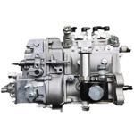
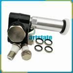
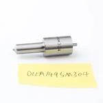
Information injection-pump assembly
BOSCH
9 400 619 485
9400619485
ZEXEL
101402-8290
1014028290
ISUZU
8973710430
8973710430

Rating:
Compare Prices: .
As an associate, we earn commssions on qualifying purchases through the links below
Car fuel pump assembly, Injection Pump For 4BG1T 8-97371043-0 101402-8290 101041-8900 Compatible For ISUZU(Silver)
ZTUVUNVA The design of the oil outlet is exquisite and reasonable, which avoids carbon deposition at the oil outlet and effectively prolongs the service life. || Reduce fuel consumption, improve jitter and accelerate smoothly. || The oil meter is accurate, which can solve the problems of abnormal oil consumption, misfire and no power. || Solve problems such as abnormal fuel meter data. || Sufficient oil return flow ensures stable pressure and sufficient cooling of the fuel system.
ZTUVUNVA The design of the oil outlet is exquisite and reasonable, which avoids carbon deposition at the oil outlet and effectively prolongs the service life. || Reduce fuel consumption, improve jitter and accelerate smoothly. || The oil meter is accurate, which can solve the problems of abnormal oil consumption, misfire and no power. || Solve problems such as abnormal fuel meter data. || Sufficient oil return flow ensures stable pressure and sufficient cooling of the fuel system.
Car fuel pump assembly, Injection Pump For 4BG1T 8-97371043-0 101402-8290 101041-8900 Compatible For ISUZU(Black)
ZTUVUNVA The design of the oil outlet is exquisite and reasonable, which avoids carbon deposition at the oil outlet and effectively prolongs the service life. || Reduce fuel consumption, improve jitter and accelerate smoothly. || The oil meter is accurate, which can solve the problems of abnormal oil consumption, misfire and no power. || Solve problems such as abnormal fuel meter data. || Sufficient oil return flow ensures stable pressure and sufficient cooling of the fuel system.
ZTUVUNVA The design of the oil outlet is exquisite and reasonable, which avoids carbon deposition at the oil outlet and effectively prolongs the service life. || Reduce fuel consumption, improve jitter and accelerate smoothly. || The oil meter is accurate, which can solve the problems of abnormal oil consumption, misfire and no power. || Solve problems such as abnormal fuel meter data. || Sufficient oil return flow ensures stable pressure and sufficient cooling of the fuel system.
Compatible with Isuzu Engine 4HF1 4BG1T Fits Fuel Injection Pump 101402-8290 8-97371043-0 101041-8900
EWAIDI Part Number: 101402-8290 8-97371043-0 101041-8900 Note: Please check the fitment carefully before purchase. Or just tell us the part number you need. || Part Name: Fuel Injection Pump || The 4BG1T diesel engine is a durable, high-performance model with low emissions. Featuring a 4.0 liter displacement and turbocharged technology, it offers superb fuel efficiency and reliability. Ideal for powering generators, construction equipment, and agricultural machinery, this engine is a cost-effective choice for demanding tasks. Its compact design and easy maintenance make it popular worldwide. || Suitable for use with Isuzu engines 4HF1 and 4BG1T. || Included in the package are one piece of Fuel Injection Pump with the following part numbers: 101402-8290, 8-97371043-0, and 101041-8900.
EWAIDI Part Number: 101402-8290 8-97371043-0 101041-8900 Note: Please check the fitment carefully before purchase. Or just tell us the part number you need. || Part Name: Fuel Injection Pump || The 4BG1T diesel engine is a durable, high-performance model with low emissions. Featuring a 4.0 liter displacement and turbocharged technology, it offers superb fuel efficiency and reliability. Ideal for powering generators, construction equipment, and agricultural machinery, this engine is a cost-effective choice for demanding tasks. Its compact design and easy maintenance make it popular worldwide. || Suitable for use with Isuzu engines 4HF1 and 4BG1T. || Included in the package are one piece of Fuel Injection Pump with the following part numbers: 101402-8290, 8-97371043-0, and 101041-8900.
You can express buy:
USD 1041.61
29-06-2025
29-06-2025
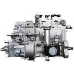
4BG1T 4BG1 Fuel inje ction pump 8-97371043-0 101402-8290 101041-8900 8973710430 For ISUZU ZEXEL 4BG1T
Images:
USD 1218.59
[01-Jul-2025]
USD 853.69

[14-Jun-2025]
USD 2369.82

[14-Jun-2025]
Service parts 101402-8290 INJECTION-PUMP ASSEMBLY:
1.
_
5.
AUTOM. ADVANCE MECHANIS
6.
COUPLING PLATE
8.
_
9.
_
11.
Nozzle and Holder
12.
Open Pre:MPa(Kqf/cm2)
18.1{185}
15.
NOZZLE SET
Cross reference number
BOSCH
9 400 619 485
9400619485
ZEXEL
101402-8290
1014028290
ISUZU
8973710430
8973710430
Zexel num
Bosch num
Firm num
Name
101402-8290
9 400 619 485
8973710430 ISUZU
INJECTION-PUMP ASSEMBLY
4BG1-T K 14BC INJECTION PUMP ASSY PE4A,5A, PE
4BG1-T K 14BC INJECTION PUMP ASSY PE4A,5A, PE
Calibration Data:
Adjustment conditions
Test oil
1404 Test oil ISO4113 or {SAEJ967d}
1404 Test oil ISO4113 or {SAEJ967d}
Test oil temperature
degC
40
40
45
Nozzle and nozzle holder
105780-8140
Bosch type code
EF8511/9A
Nozzle
105780-0000
Bosch type code
DN12SD12T
Nozzle holder
105780-2080
Bosch type code
EF8511/9
Opening pressure
MPa
17.2
Opening pressure
kgf/cm2
175
Injection pipe
Outer diameter - inner diameter - length (mm) mm 6-2-600
Outer diameter - inner diameter - length (mm) mm 6-2-600
Overflow valve
131424-4920
Overflow valve opening pressure
kPa
127
107
147
Overflow valve opening pressure
kgf/cm2
1.3
1.1
1.5
Tester oil delivery pressure
kPa
157
157
157
Tester oil delivery pressure
kgf/cm2
1.6
1.6
1.6
Direction of rotation (viewed from drive side)
Right R
Right R
Injection timing adjustment
Direction of rotation (viewed from drive side)
Right R
Right R
Injection order
1-3-4-2
Pre-stroke
mm
3.4
3.35
3.45
Beginning of injection position
Drive side NO.1
Drive side NO.1
Difference between angles 1
Cal 1-3 deg. 90 89.5 90.5
Cal 1-3 deg. 90 89.5 90.5
Difference between angles 2
Cal 1-4 deg. 180 179.5 180.5
Cal 1-4 deg. 180 179.5 180.5
Difference between angles 3
Cyl.1-2 deg. 270 269.5 270.5
Cyl.1-2 deg. 270 269.5 270.5
Injection quantity adjustment
Adjusting point
A
Rack position
8.9
Pump speed
r/min
1100
1100
1100
Average injection quantity
mm3/st.
94
92.9
95.1
Max. variation between cylinders
%
0
-2
2
Basic
*
Fixing the lever
*
Injection quantity adjustment_02
Adjusting point
-
Rack position
6.3+-0.5
Pump speed
r/min
500
500
500
Average injection quantity
mm3/st.
12
10.6
13.4
Max. variation between cylinders
%
0
-14
14
Fixing the rack
*
Remarks
Adjust only variation between cylinders; adjust governor according to governor specifications.
Adjust only variation between cylinders; adjust governor according to governor specifications.
Injection quantity adjustment_03
Adjusting point
D
Rack position
9.1++
Pump speed
r/min
100
100
100
Average injection quantity
mm3/st.
125
120
130
Fixing the lever
*
Rack limit
*
Test data Ex:
Governor adjustment
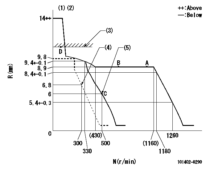
N:Pump speed
R:Rack position (mm)
(1)Target notch: K
(2)Tolerance for racks not indicated: +-0.05mm.
(3)RACK LIMIT
(4)Set idle sub-spring
(5)Main spring setting
----------
K=16
----------
----------
K=16
----------
Speed control lever angle
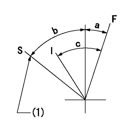
F:Full speed
I:Idle
S:Stop
(1)Stopper bolt setting
----------
----------
a=7deg+-5deg b=35deg+-5deg c=21deg+-5deg
----------
----------
a=7deg+-5deg b=35deg+-5deg c=21deg+-5deg
Stop lever angle
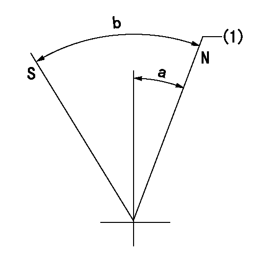
N:Pump normal
S:Stop the pump.
(1)Normal
----------
----------
a=13deg+-5deg b=53deg+-5deg
----------
----------
a=13deg+-5deg b=53deg+-5deg
Timing setting

(1)Pump vertical direction
(2)Position of gear mark 'CC' at No 1 cylinder's beginning of injection
(3)B.T.D.C.: aa
(4)-
----------
aa=9deg
----------
a=(100deg)
----------
aa=9deg
----------
a=(100deg)
Information:
Bearings
Anti-Friction Bearings
When an anti-friction bearing is removed, cover it to keep out dirt and abrasives. Wash the bearings in nonflammable cleaning solution and allow them to drain dry. The bearings may be dried with compressed air, but DO NOT SPIN THE BEARING. Discard the bearings if the races and balls or rollers are pitted, scored or burned. If the bearing is serviceable, coat it with oil and wrap it in clean paper. DO NOT unwrap new bearings until time of installation.The life of an anti-friction bearing will be shortened if not properly lubricated.Double Row, Tapered Roller
Double row, tapered roller bearings are precision fit during manufacture and the components are not interchangeable. The cups, cones and spacers are usually etched with the same serial number and letter designator. If no letter designators are found, wire the components together to assure correct installation. Reusable bearing components should be installed in their original positions.Heating Bearings
Bearings which require expansion for installation should be heated in oil not to exceed 121°C (250°F). When more than one part is heated to aid in assembly, they must be allowed to cool and then pressed together again. Parts often separate as they cool and shrink.Installation
Lubricate new or used bearings before installation. Bearings that are to be preloaded must have a film of oil over the entire assembly to obtain accurate preloading. When installing a bearing, spacer or washer against a shoulder on a shaft, be sure the chamfered side is toward the shoulder. When pressing bearings into a retainer or bore, apply pressure to the outer race. If the bearing is pressed on the shaft, apply pressure on the inner race.Preload
Preload is an initial force placed on the bearing at the time of assembly.Determine preload or end clearance form the Specifications Section of this Service Manual. Care should be exercised in applying preload. Misapplication of preload to bearings requiring end clearance can result in bearing failure.Sleeve Bearings
DO NOT INSTALL SLEEVE BEARINGS WITH A HAMMER. Use a press, if possible and apply the pressure directly in line with the bore. If it is necessary to drive on a bearing, use a driver or a bar with a smooth flat end. If a sleeve bearing has an oil hole, align it with the oil hole in the mating part.
Have questions with 101402-8290?
Group cross 101402-8290 ZEXEL
Isuzu
101402-8290
9 400 619 485
8973710430
INJECTION-PUMP ASSEMBLY
4BG1-T
4BG1-T


